Documentation for the latest CamBam release is available here...
Drawing Surfaces
The 3D surface and solid modelling functionality of CamBam is limited, but there are number of helpful 3D drawing routines.
These are available from the Draw - Surface menu.
From Mesh File
This inserts a 3D surface from an STL file.
From Bitmap
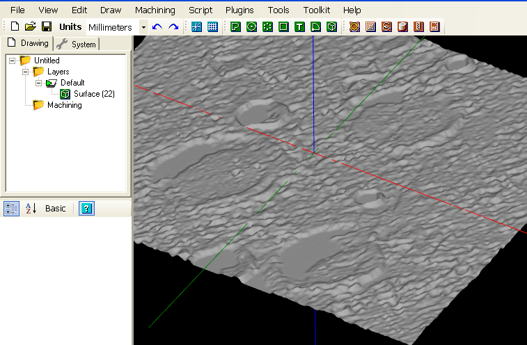
Converts a bitmap image into a 3D surface by using the brightness levels to define the Z heights.
This is a similar process used by the Heightmap Plugin, but where the plugin will only generate an engraving toolpath,
the draw surface from bitmap routine will create a 3D mesh that can be used to create more sophisticated 3D machining
operations such as waterline and scanline roughing.
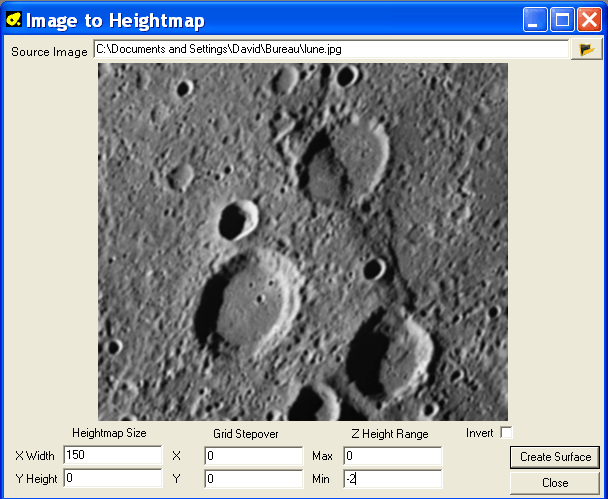
Click the  button to open an image file.
Heightmap Size:
Set the X and Y dimensions (in current drawing units) of the surface to be generated. If the X or Y dimension is left at 0, this dimension
will be automatically calculated so as to preserve the aspect ratio of the original image.
Grid Stepover: Controls the size of each triangular facet that will be used to build the surface. If this is set to 0, the
size will be based on one image pixel size.
Z Height range: The minimum and maximum Z heights that correspond to the lightest and darkest parts of the image.
Invert: When unticked, dark areas represent low Z values and light areas higher Z areas. If invert is ticked
this is reversed.
Click Create surface to generate the 3D mesh into the current drawing.
From text file
Allows you to use a plain text file (ASCII) providing a list of coordinates representing the triangle faces of a 3D object.
Each line consists of nine coordinates, separated by a space, corresponding to the coordinates X, Y and Z of three vertices defining a triangle.
Example:
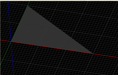
0 0 0 0 20 0 30 0 0
This defines 3 points : Point1 (x,y,z) = 0,0,0 Point2 = 0,20,0 and Point3 = 30,0,0
This file gives the following result:
Extrude
Extrude is used to create a 3D surface from a 2D line by projecting it in the Z direction.
This operation was originally added to create shapes for use as holding tabs or 'sprues' on 3D machining operations.
To create extrusions along other axis, the shape must first be extruded in Z, then rotate the extruded surface object to the required orientation.
The Extrude operation will first prompt for an Extrusion Height. This will be the Z height of the extruded surface.
A positive height will extend toward the positive Z axis (ie toward the viewer when drawing is in the normal orientation with the XY
plane parallel to the screen). A negative height will extend the surface along the negative Z axis (ie into the screen).
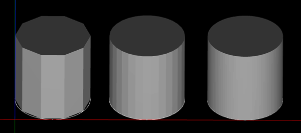
The routine next prompts for the Extrusion Steps. This controls the number of steps around the source shape to insert faces
on the extruded surface. More steps will result in a smoother surface.
This following image of a circle extrusion shows steps of 10, 30 and 100.
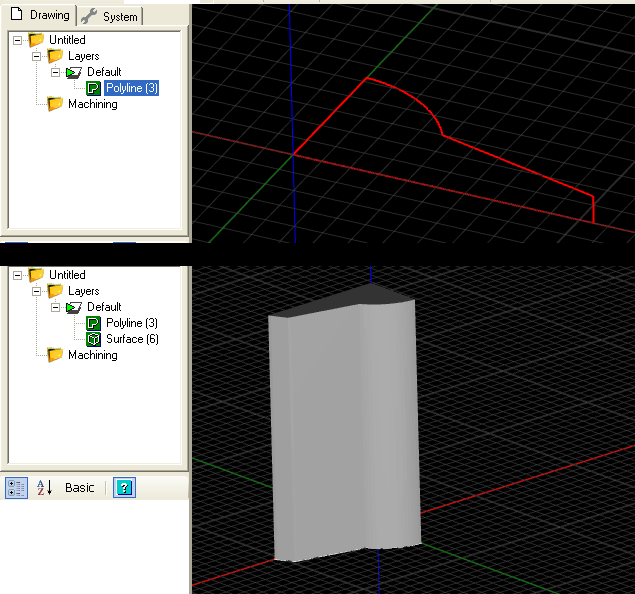
Another example of an extruded polyline.
