Documentation for the latest CamBam release is available here...
Tutorial: Bitmap Heightmaps
This tutorial describes using the Heightmap plugin to generate pseudo 3D profiles from bitmaps.
The same routine can also be used to generate photo engravings in two-toned materials and lithopanes.
The source code for the heightmap plugin is also provided with CamBam for the adventurous.
Warning: The Heightmap plugin can produce gcode that plunges the full depth of your heightmap in one go.
The engraving machining operation now supports a Depth Increment property that can be used to machine deep height maps
in multiple passes. Another alternative is to use the Draw - Surface - From Bitmap operation to create a 3D surface mesh
which can be used with the 3D machining operations.
Step 1 - Open the Heightmap plugin
The height map plugin is accessed from the Plugins - HeightMap Generator option from the top menu.
CamBam Plugins are .NET class library .DLLs and are located in a plugin subfolder in the CamBam application folder; Typically:
C:\Program Files\CamBam plus 0.9.8\plugins
The source code for the Heightmap generator can also be found in a zip file in this folder.
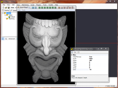
Step 2 - Select a Bitmap File.
The success of a Heightmap depends largely on the quality of the source bitmap. Front lit objects with even shading usually work best.
Inspired by the inimitable greybeard's experiments in the cnczone 3D for Crazies thread,
I photographed an object submerged in a tray containing water and blue food colouring. I then used a drawing program to filter the bitmap to
just show the red channel as a greyscale image. In theory, the further the item is from the surface of the liquid, the more blue it will appear.
This worked much better than I expected although care must be taken to avoid surface reflections and air bubbles. This is perhaps not such
a good idea for making heightmaps of people.
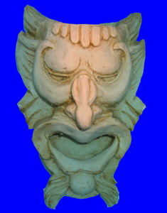
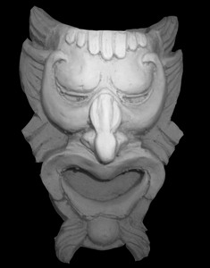
With the Heightmap generator window open, select File - Open from the top menu and select the source image.
Step 3 - Heightmap Options
Change the heightmap options from the Heightmap plugin's Tools - Options top menu.
Here is an explanation of the properties
|
ClearPrevious
|
The Tools - Generate Heightmap menu option from the heightmap form can be called multiple times.
If this option is set True, the heightmap previously created will be removed before a new heightmap is generated.
|
|
Invert
|
If True then darker colours are higher (larger Z values), otherwise lighter colours are higher.
|
|
XSize / YSize
|
Width (X) and Height (Y) of the heightmap in the same units as the current CamBam drawing.
These values control the actual physical size of the resulting heightmap. If the YSize is set to 0, the aspect ratio of
the bitmap will be applied to the XSize value to determine the Y height.
Examples:
XSize = 100 (mm), YSize = 0
XSize = 4 (inches), YSize = 0
|
|
XStep / YStep
|
A heightmap creates a series of scan lines, much the same as how a television image is created.
The YStep value controls how far apart the horizontal scan lines are and the XStep values determines how far apart each point
in the line is in the X direction.
If either is set to 0, the height will be calculated at each pixel point.
Examples
XStep = 0, YStep = 0
(calculate height at each bitmap pixel)
XStep = 0, YStep = 0.75 (mm)
(calculate height at each pixel in one scan line, with each horizontal scanline 0.75mm apart)
XStep = 0, YStep = 0.001 (inches)
(calculate height at each pixel in one scan line, with each horizontal scanline 0.001in apart).
|
|
Zmax
|
This is the highest Z depth.
If the stock surface is used to zero the Z axis, then ZMax would typically be zero as well.
|
|
Zmin
|
This is the deepest Z depth and represents the Z coordinate of the deepest cuts in the heightmap.
Examples
ZMax = 0, ZMin = -10 (mm)
The heightmap heights will range from -10mm at the deepest to 0mm at the highest points.
ZMax = 0.125 (inches) ZMin = -0.125 (inches)
The heightmap heights will range from -0.125in at the deepest to 0.125in at the highest points.
|
Step 4 - Generate Heightmap
Close the options window and select Tools - Generate Heightmap.
You should see some lines appear in the underlying CamBam drawing. Leave the Heightmap generator window open and rotate and scale the CamBam drawing to get a better idea of the Heightmaps dimensions.
More information on rotating, panning and zooming the drawing view can be found here...
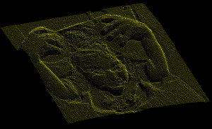
Here is a screenshot of the resulting heightmap.
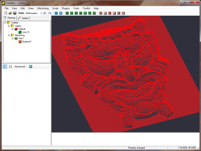
As well as generating a 3D Line object that contains the resulting heightmap, the plugin also creates an engraving machine operation linked to this line. An engraving operation is used as these are designed to 'follow' the associated geometry. In effect it is using the 3D line as a toolpath.
Change the Engraving machine operation parameters such as cutting feedrates.
NOTE: Do not change the engraving target depth value, the cutting depth is taken from the source line.
To convert the heightmap into gcode for your machine, right click the Machining group in the CamBam tree view then select the Create GCode File menu option.
Here is the very first Heightmap I produced from CamBam. The image is 120mm X 90mm using a 2mm flat bit in plywood. Not fantastic to look at but at least there were no disasters.
I will try to find some nice examples.
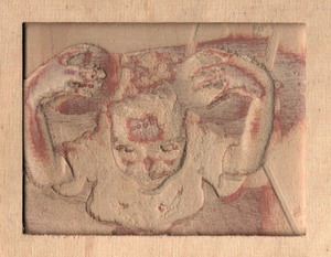
Photo Engraving
The heightmap process can also generate shaded engravings from bitmaps.
A V cutter is used, usually into a 2 tone engraving laminate. The deeper the cutter, the wider the cut and darker it will appear (if using a light on dark laminate).
The Z depth needs only be small (~0.5mm, 0.02in). The YStep stepover should be increased so the 'scan lines' do not overlap
and spoil the shading effect. This distance will vary depending on the V cutter angle and depth. For a 60 degree cutter at 0.5mm
I use a 0.7mm YStep.

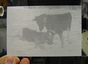
A lithopane is another variation on this theme, where an image is engraved into a thick translucent material and viewed with back lighting. Lithopanes are typically inverted with the deeper cuts
resulting in thinner material and more light shining through.
Creating a Point Cloud From a Heightmap
Here is a method to generate a DXF point cloud
Generate a heightmap polyline as per usual and select the line if it is not already.
Now do Draw - Point List - Step Around Geometry. from the drawings context menu.
This will insert a point along the line every N step distance.
By default, the heightmap will do 1 bitmap pixel = 1 drawing unit (This can be changed in the heightmap options).
I entered 1 for the step distance then pressed OK.
CamBam currently displays points using biggish squares so it will look cluttered, but don't worry about that.
The line object can now be deleted.
The drawing can now be exported to a DXF file. Here a heightmap pointcloud is viewed in AutoCAD.
