Documentation for the latest CamBam release is available here...
Edit Surface
This section describes the operations available from the Edit - Surface menu.
Plane Slice X, Y, Z
These functions obtain polylines from a 3D object by slicing the object along a given axis.
Plane slices provide a useful way of generating 2D machining operations from 3D models, without having to redraw the
models in 2D. For many engineering or prismatic 3D shapes, 2D machining operations can provide much simpler, faster and more accurate
operations than the 3D machining operations.
The following examples show plane slice being used to create a combination of 2D and 3D machining operations from a 3D model.
Here is the original model object, created within SolidWorks ®.
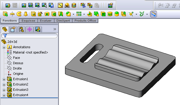
The model is then loaded into CamBam.
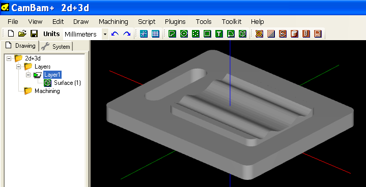
The wavy part of the model will be machined using 3D operations, but it would be more efficient to use 2D operations
on the flat parts of the model.
Plane Slice Z is used to slice the model along planes, normal to the Z axis, at 5mm intervals.
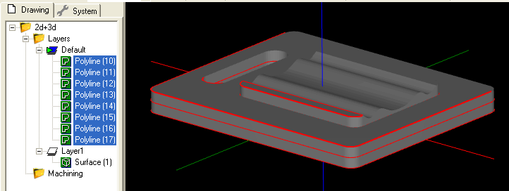
It is good practice to create a new layer to receive the plane slice polylines, to make the drawing more manageable and
so that the polylines may be viewed and manipulated independently of the original 3D surface.
In this example, we are only interesting in a selection of the plane sliced polylines (shown highlighted below). The other
polylines can be deleted. The layer containing the 3D surface has also been hidden for clarity.
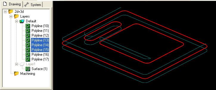
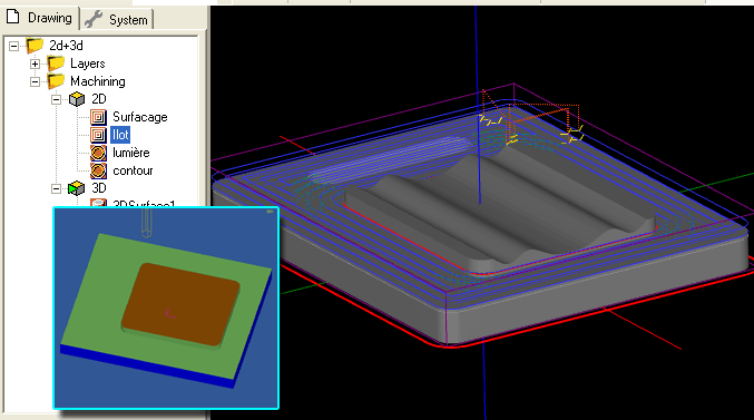
2D pocket operations are used to clear the flat areas of the mode. The inset image shows the results when simulated using
CutViewer Mill.
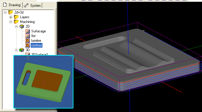
2D profiles are then used for cutting slots and the outer shape.
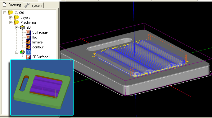
A 3D surface operation is then used for the wavy area of the shape. The inner plane slice polyline is used to restrict
the 3D surface by specifying a boundary shape. See the 3D tutorial for more information on this operation.
Silhouette
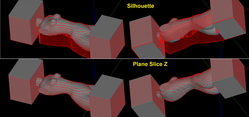
A Silhouette is similar to a plane slice operation, except overhanging areas of the model from higher layers are projected downwards. These
represent the limits of parts of the model accessible by a cutting tool. The silhouette routines can only be used for the Z axis.
A comparison of Silhouette (top) and Plane Slice Z (bottom).
Invert Faces
Invert Faces will reverse the direction of face normals for each selected surface.
3D Meshes are built from many triangular faces. Each triangle has a 'normal', which is a direction vector perpendicular to the triangular face.
The order of the points around the triangle will determine the normal direction.
CamBam uses a 'Right Hand Rule', so that if the fingers of your right hand curl in the direction that the triangle points are ordered,
your thumb will point in the direction of the normal.
Normal vectors are used to determine the outside facing direction of each face. When displaying meshes, faces pointing away from the
viewer are often ignored by the display routines. If meshes are wound using a 'Left Hand Rule', this can result in the models
appearing dark or hard to see in the CamBam drawing display.
Edge Detect
Will dump edge lines detected from selected 3D meshes.
These are triangle faces edges that have no neighbours, or the neighbouring face forms an angle.
Project Lines to Surface
Selected drawing shapes will be projected onto any selected surface objects.
The routine prompts for a Projection Resolution. This is the distance along each drawing line at which the Z height is tested.
If a point along the line is outside any surfaces, the minimum depth of all selected surfaces is used.