 Bitmap Objects
Use Draw - Bitmap, then select a drawing file such as a jpeg or bitmap. CamBam will detect edges in the bitmap, allowing you to scan a drawing, or draw a shape in an external application like Photoshop, then load it into CamBam and insert a machining operation based from it. Changes to the drawing will be picked up automatically by the machining operation.
The bitmap file is linked to the CamBam drawing, not saved within it, so transferring CamBam drawings containing bitmaps will also require the bitmap file to be copied.
To break the link to a bitmap file and include the vectors within the CamBam drawing, select the drawing object then use Convert To Polylines or CTRL+P.
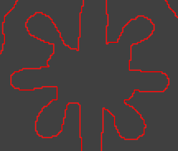
Showing Bitmaps or Vectors
The
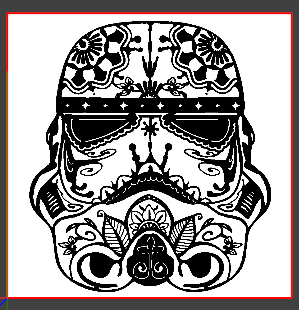 showing bitmap only |
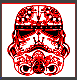 showing bitmap and vectors |
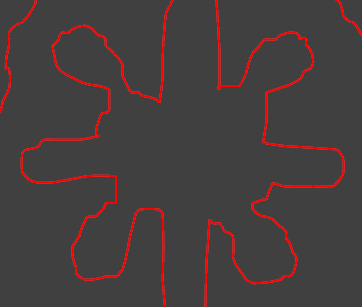
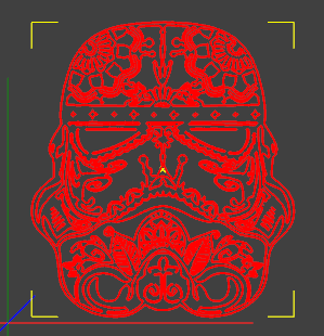 showing vectors only (invert=false) |
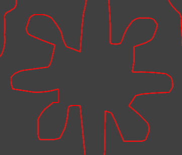
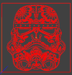 showing vectors only (invert=true) |
Smoothing
CamBam will automatically vectorize the bitmap using a quick and simple edge detect.
You can change the vectorization method in the bitmap properties. Selecting
Smoothing Pixels can be used to control the spline fit.
Small smoothing pixel values (around 1), can take a very long time to calculate (minutes!).
We are working to make this faster and run in a background process so as not to lock up the UI, but for now smoothing pixel settings of 2 or more are recommended.
 no smoothing |
 smooth pixels = 1 |
 smooth pixels = 2 |
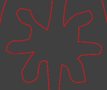 smooth pixels = 5 |
Properties
|
|
Controls whether the bitmap image is displayed. |
|
|
Controls whether the detected edge vectors are displayed. |
|
|
The height of the image in drawing units. The pixel height and vertical resolution stored in the bitmap are used to calculate the default height value. |
|
|
The width of the image in drawing units. The pixel width and horizontal resolution stored in the bitmap are used to calculate the default width value. |
|
|
If If |
|
|
This is the X,Y,Z drawing location of the lower left corner of the bitmap. |
|
|
If Smaller values will produce splines that closely match the outline, but may take longer to calculate, produces larger splines and possibly result in unwanted detail such as jagged pixel outlines. Larger values will produce faster, simpler, smoother curves but with less accuracy. |
|
|
If If Raw pixel edges will be faster to calculate, but result in 'jagged' pixel edges. |
|
|
The path to the source bitmap file. The following bitmap formats are supported: The filename will be relative to the current CamBam drawing path. Saving the CamBam drawing first, before inserting bitmaps is recommend so the relative rather than full paths will be detected. Relative paths make is easier to copy the .cb file and bitmap files together without needing to change paths within the drawing. |
|
|
The brightness threshold used to determine if a pixel is set when vectorizing. A value between 0 and 1, where 0 is black and 1 is white. Note that color images use monochrome edge detection so edges between different colors with similar brightnesses may not be detected. |
|
|
A general purpose, multi-line text field that can be used to store notes or parameter data. |
|
|
A 4 x 4 matrix of numbers used for general transformations of the drawing objects. The transform matrix can be used for rotations, translations and scaling about all 3 axis. |