CAD Entities
 Polyline
Polylines consist of multiple straight line and circular arc segments.
Polylines are used internally to represent toolpath shapes as they correspond well to gcode G1 (line) and G2,G3 (arc) moves.
The polylines are drawn with the mouse, making a left click to place the points. A double click on a polyline enter in edit mode and allow to see and to move the points which constitute it.
Click the middle mouse button (wheel) or hit Enter to confirm, or Esc to cancel.
Properties
|
|
Note Polylines with first and last points having the same coordinates are not necessarily closed. The closed marker should
be set to |
|
|
This property contains a collection of polyline points. Clicking the [...] button to the right of the property will open up a window where the points can be edited directly. Each point contains an X,Y and Z coordinate and a bulge parameter. |
|
|
A general purpose, multi-line text field that can be used to store notes or parameter data. |
|
|
A 4 x 4 matrix of numbers used for general transformations of the drawing objects. The transform matrix can be used for rotations, translations and scaling about all 3 axis. |
 Region
A region consists of a closed outer shape and a number of internal holes.
To create a region, select inner and outer shapes then use the Edit - Convert - To Region menu option, or press CTRL+R
 Circle
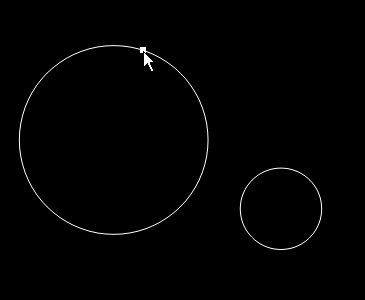
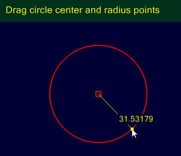
The circles are drawn with the mouse, making a left click to place the center, then after releasing the left button, moving the mouse to define the radius followed by a new click of the left button to finish.
New 1.0
A double click on a circle enter in edit mode and thus to see and move the center; click / move the center point to move it ; click / move around the circle to change its diameter.
Click the middle mouse button (wheel) or hit Enter to confirm, or Esc to cancel.
Properties
|
|
The coordinates of the center of the circle. |
|
|
The diameter of the circle. |
|
|
A general purpose, multi-line text field that can be used to store notes or parameter data. |
|
|
A 4 x 4 matrix of numbers used for general transformations of the drawing objects. The transform matrix can be used for rotations, translations and scaling about all 3 axis. |
 PointList
Point lists are useful for defining points to be used for drilling operations.
A double click on a pointList allows you to enter in edit mode and to move or add points; click / move a point to move it ; click on a the drawing area to add a new one.
Click the middle mouse button (wheel) or hit Enter to confirm, or Esc to cancel.
As well as drawing directly, they can be created from the Draw-Point List menu operations
| Divide Geometry |
Evenly divides a selected shape into a given number and inserts a point at each division. This is useful for generating a bolt hole pattern. |
| Step Around Geometry |
Inserts a point at given distances around a selected shape. |
| Fill Geometry |
Fills a closed shape with points. |
| Offset Fill Geometry |
Fills a closed shape with points where alternating rows are offset by half the stepping distance. |
| Centers |
Inserts a point at the center of each selected object. |
| Extents |
Inserts a point at the extremities and center of a boundary rectangle enclosing each selected object. |
Properties
|
|
This property contains a collection of points. Clicking the [...] button to the right of the property will open up a window where the points can be edited directly. |
|
|
A general purpose, multi-line text field that can be used to store notes or parameter data. |
|
|
A 4 x 4 matrix of numbers used for general transformations of the drawing objects. The transform matrix can be used for rotations, translations and scaling about all 3 axis. |
 Rectangle
The rectangles are drawn with the mouse, making a left click to place an angle, then after releasing the left button, moving the mouse to define the diagonal followed by a new click of the left button to finish.
A double click on a rectangle enter in edit mode and alow to move the points of angles (the object remains rectangular)
Click the middle mouse button (wheel) or hit Enter to confirm, or Esc to cancel.
Properties
|
|
This will round the corners of the rectangle to a given radius. |
|
|
The height of the rectangle. |
|
|
The coordinates of the lower left corner of the rectangle. |
|
|
The width of the rectangle. |
|
|
A general purpose, multi-line text field that can be used to store notes or parameter data. |
|
|
A 4 x 4 matrix of numbers used for general transformations of the drawing objects. The transform matrix can be used for rotations, translations and scaling about all 3 axis. |
 Text
Text
Properties
|
|
Bold Font Style. |
|
|
This option scales the width used for each character. The default is 1. A setting of 2 would double the space used for each character (but not the character itself). |
|
|
This is the name of the font to use for the text. |
|
|
This is the text height in drawing units. The height is based on the em square, which is a property of the font that describes the largest dimensions possible of the font. To obtain an accurate height, given the text and font entered, the Edit - Resize command should be used. |
|
|
Italic Font Style. |
|
|
This scales the distance between each text line. The default is 1. |
|
|
This is the first and at the moment, only alignment point. The TextAlignmentH and TextAlignmentV options are all relative to this point. |
|
|
Regular Font Style. |
|
|
A general purpose, multi-line text field that can be used to store notes or parameter data. |
|
|
The text to enter. To enter multi line text, click the [...] button after this property. |
|
|
|
|
|
|
|
|
A 4 x 4 matrix of numbers used for general transformations of the drawing objects. The transform matrix can be used for rotations, translations and scaling about all 3 axis. |
 Arc
Arc
The arcs are drawn with the mouse by clicking the two extreme points, then by positioning the center with a third click.
New 1.0
A double click on an arc allows you to enter in edit mode and to move its center start and end points.
Click the middle mouse button (wheel) or hit Enter to confirm, or Esc to cancel.
Note: While drawing or editing an arc, pressing the Shift key will invert the direction of the arc when moving the center.
Properties
|
|
The center of the arc. |
|
|
The radius of the arc. |
|
|
The start angle in degrees of the first arc point. Angle = 0 is along the positive X axis. |
|
|
The sweep angle in degrees from the first to second arc point. Positive angles are counter clockwise and negative angles clockwise. |
|
|
A general purpose, multi-line text field that can be used to store notes or parameter data. |
|
|
A 4 x 4 matrix of numbers used for general transformations of the drawing objects. The transform matrix can be used for rotations, translations and scaling about all 3 axis. |
 Line
Line
Lines have multiple segments, similar to polylines, but can only contain straight sections.
New 1.0
Lines can be edited by double-clicking on it, like polylines
 Surface
These are triangular faceted 3D meshes imported from an STL or 3DS file
New 1.0
They also can be created in CamBam with Draw/Surface/extrude solids and Draw/Surface/Fill
Surfaces are triangle face meshes imported from STL and 3DS files.
 Spline
Splines (or NURBS) are curves that are defined by a series of control points and weights.
New 1.0
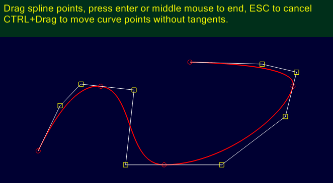
The splines are drawn with the mouse, making a left click to place the points of inflection.
A double click on a spline enter in edit mode and thus to see and move the control points that constitute it, as well as the points that make it possible to modify the curvature locally.
Pressing the Ctrl key while moving a control point (red circle) temporarily breaks the link with its curvature control points (yellow squares)
Click the middle mouse button (wheel) or hit Enter to confirm, or Esc to cancel.
 Script object
New 1.0
 Bitmap object
New 1.0
Draw/More
Tangent
Draws a line between points of tangency of circles or arcs (or arcs contained in a polyline)
After choosing the Tangent function, move the mouse over the first circle / arc; the end of the line will follow and stick to the curve ; click the left mouse button to fix that first point (which will “slide” along the curve depending on the orientation you give to the line)
Then move the mouse cursor on the second circle / arc; a triangle will appear at the nearest point of tangency. This triangle will change places depending on the position of the mouse.
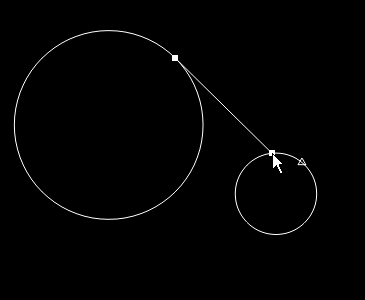
Hook the end of the line on the triangle, then click on the left button to finish.
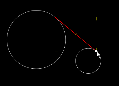
Note: It may be easier to “feel” the magnetization to the curve/triangle if you disable grid snapping
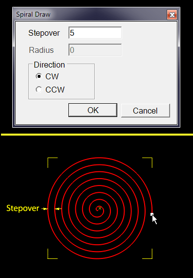
Flat Spiral
Draws a flat spiral.
The
The
After filling in these two informations, draw the spiral starting at the center and then defining the radius (as if to draw a circle)
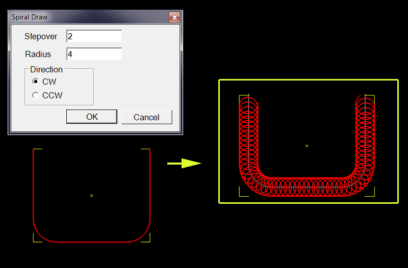
Spiral Path
Draws a spiral along a path.
First, select a shape that will serve as path, then choose the Spiral Path command from the menu.
The same window as for a flat spiral will open. It allows to choose the
Trochoidal Path
Same principle as above, but this time it is a succession of arcs that follow the path, and not a spiral.
Combined with an engraving operation, this path allows you to quickly remove material with less stress for the tools.
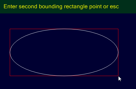
Ellipse
Allows drawing ellipses by drawing a bounding rectangle with the mouse.
The ellipse once drawn becomes a polyline, consisting of arcs and lines.