 Lathe Machining Operation
Note: The lathe code is new to version 0.9.8 and is still undergoing testing and development.
Treat any lathe gcode with caution and run simulations or air cuts before machining.
The Lathe machining operation has been provided as a plugin. In this way the plugin can be developed and updated independently of the main CamBam application. It is also a demonstration of the ability to extend CamBam’s machining capability using user written plugins.
The file lathe-test.cb in the CamBam samples folder demonstrates the new lathe operation.
In this initial lathe release there are a number of limitations:
- Only profiling operations are currently supported. No facing, boring or threading support yet.
- Apart from the tool radius, there is no mechanism to define a lathe tool shape. The part should be drawn to allow for the cutter size and shape.
Drawing
A lathe profile can be generated from a 2D line representing the shape to machine.
The shape should be drawn so that:
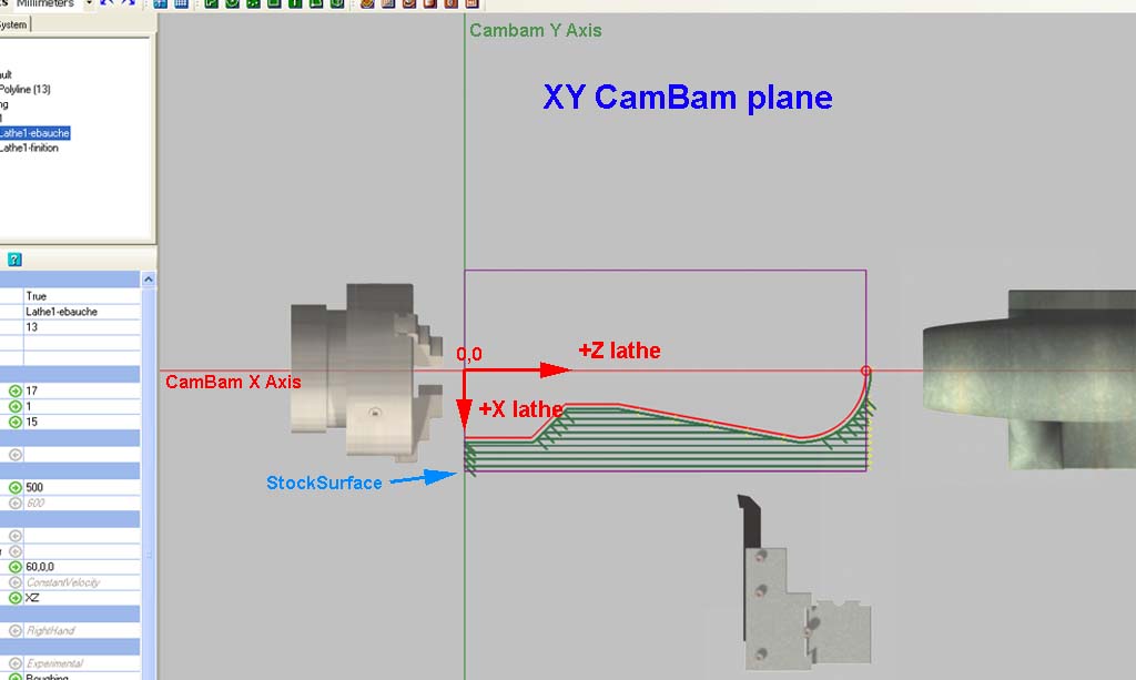
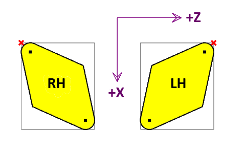
The lathe +X axis is drawn in the -Y direction and
The lathe +Z axis is drawn in the +X direction.
This is so that the drawing will appear in the same orientation as when standing in front of a conventional lathe.
The toolpaths will be converted to standard lathe X and Z coordinates when the gcode is produced.
Only draw the profile line to be cut. Do not draw closed polylines, mirrored lines on the opposite side of the turning axis or lines along the turning axis as the lathe operation will try to cut these as well which will cause problems.
The profile line can be drawn anywhere in the drawing. If this line is away from the origin, the Machining Origin should be set so that it lies on the axis of rotation and at the Z=0 (lathe coordinate).
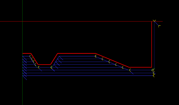
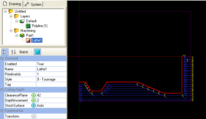
An example showing a profile where the machining 0,0 point is the same as the drawing origin.
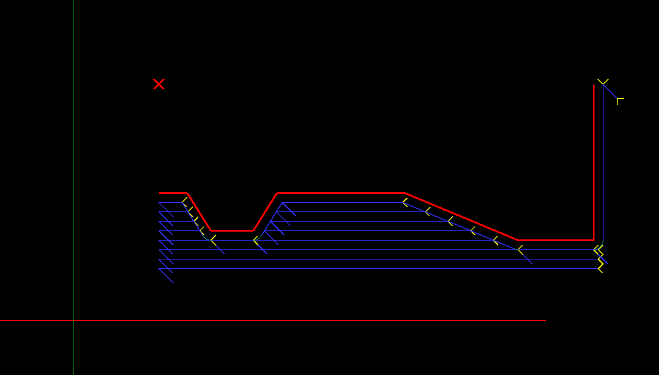
The same pattern drawn away from the origin, where the machining origin (red X) has been moved to indicate the lathes X=0, Z=0 point.
You can set the machine zero by setting MachiningOrigin property of the machining or part objects.
Click the  button to the right of the MachiningOrigin property to select the machine zero
point on the drawing.
button to the right of the MachiningOrigin property to select the machine zero
point on the drawing.
Stock Object
The lathe operation can use information from the stock object if one is defined, to determine properties such as stock surface and the machining envelope.
CamBam’s stock definition does not currently support cylindrical stock so the stock will be shown as a rectangular block.
The following image shows a stock objects of 9-mm diameter and 100mm long (purple cube).
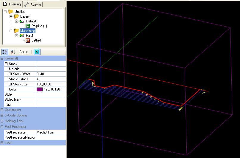
If the Stock Surface property is set to Auto, the stock object size is used to define it.
- The X size will be the length of the stock (along the lathe’s Z axis).
- The Z and Y size should both be set to the stock diameter.
- StockSurface should be set to the stock radius.
- The Stock offset Y value should be set to negative the stock radius.
Using the Lathe Operation
Select a suitable profile line, then insert a lathe operation by selecting the top Machining menu, then select  Lathe.
Note - The lathe plugin does not currently add an icon to the toolbar or drawing context menu.
Make sure the following are set:
- Workplane is set to XZ.
- Stock surface equals the radius of the stock.
- Clearance plane is greater than the radius of the stock.
- The machining origin is set along the axis of rotation.
- The tool diameter is set to twice the tool nose radius.
- The tool profile is set to Lathe.
- The correct RoughingFinishing option is set.
- If Roughing, a small RoughingClearance value is set.
- DepthIncrement and feedrates are appropriate for the material.
- Define the stock object if needed.
- A suitable post processor such as Mach3-Turn or EMC-Turn are selected in the Machining properties.
Properties
|
|
The safe X lathe coordinate to avoid any stock. The clearance plane value should always be expressed as a radius. |
|
|
A multi-line gcode script that will be inserted into the gcode post after the current machining operation. |
|
|
A multi-line gcode script that will be inserted into the gcode post before the current machining operation. |
|
|
The feed rate to use when cutting. |
|
|
When roughing, this is the radial X distance between each parallel cut. |
|
|
|
|
|
|
|
New [0.9.8N] |
Controls the length of the 45 degree lead in moves. A zero value will disable these moves. |
|
New [0.9.8N] |
Controls the length of the 45 degree back away moves. A zero value will disable these moves. |
|
|
Maximum distance as a fraction (0-1) of the tool diameter to cut in horizontal transitions. If the distance to the next toolpath exceeds MaxCrossoverDistance, a retract, rapid and plunge to the next position, via the clearance plane, is inserted. |
|
|
Each machine operation can be given a meaningful name or description. |
|
|
An option that controls how the toolpaths are ordered in gcode output.
|
|
|
The feed rate to use when plunging. |
|
|
List of drawing objects from which this machine operation is defined. |
|
|
The |
|
|
This is the amount of stock to leave after the final cut. Remaining stock is typically removed later in a finishing pass. Negative values can be used to oversize cuts. |
|
|
The direction of rotation of the spindle. |
|
|
The pulley number or dial setting of the spindle for the target speed. |
|
|
The speed in RPM of the spindle. |
|
|
Used to select a point, near to where the first toolpath should begin machining. |
|
|
This is the X offset of the stock surface at which to start machining. Can be set explicitly or determined from the stock object. Stock surface should always be expressed as a radius. |
|
[New! 0.9.8] |
Select a CAM Style for this machining operation. All default parameters will be inherited from this style. |
|
|
A general purpose, multi-line text field that can be used to store notes or parameter data. |
|
|
This is the diameter of the current tool in drawing units. If the tool diameter is 0, the diameter from the tool information stored in the tool library for the given tool number will be used. |
|
|
The ToolNumber is used to identify the current tool. If ToolNumber changes between successive machine ops a toolchange instruction is created in gcode. ToolNumber=0 is a special case which will not issue a toolchange. The tool number is also used to look up tool information in the current tool library. The tool library is specified in the containing Part, or if this is not present in the Machining folder level. If no tool library is defined the Default-(units) tool library is assumed. |
|
|
The shape of the cutter. The new
If the tool profile is |
|
|
Instructs the gcode interpreter whether or to use look ahead smoothing.
|
|
|
Should always be set to XZ for lathe code! |
Post Processor
Three sample lathe specific post processor definitions have been provided : Mach3-Turn, Mach3-Turn-CV (Mach3 with CutViewer definitions) and EMC2-Turn.
These definitions may need to be customised to suit the configuration of those controllers.
This section describes some post processor properties that are relevant to customising the lathe gcode output.
|
|
Used to specify which direction clearance moves are made. Usually Z for normal milling, but must be set to X for lathe turning operations. |
|
|
Controls whether the X lathe coordinates will be written to gcode as
|
|
|
If If
In the diagram above, the red cross represents the toolpath reference point when |
|
|
Code to use to set X diameter mode (eg G7 for LinuxCNC) |
|
|
Code to use to set X radius mode (eg G8 for LinuxCNC) |
|
|
If set |
|
|
|
Tool Definitions
A sample lathe tool library ‘Lathe-mm’ is provided. The tool library can be selected by changing the
Tool libraries are currently designed to support milling cutters, rather than lathe. However there are a couple of parameters than are useful to store in the tool library.
should always be set to the new
A new
For example. CutViewer Turn recognises a gcode comment that defines the geometry of the lathe tool in the following format:
TOOL/STANDARD,BA,A,R,IC,ITP
Refer to the CutViewer Turn documentation for details of this description. Here is a summary of the parameters:
- BA - Back angle.
- A - Angle.
- R - Radius.
- IC - Inner circle.
- ITP - Imaginary Tool Point. 0=Tool Center, 3 for right hand offset, 4 left hand offset.
This example
{$comment} TOOL/STANDARD,40,40,{$tool.radius},2,3 {$endcomment}