Tutorial: Drilling
Creating drilling patterns is very easy. Here a Wingding font character ‘N’ is used to create a drilling pattern for an external hard disk enclosure.
Download the files used in this tutorial
Step 1 - Insert text
Drilling machine operations are based on point lists or circle centers. There are a number of routines in CamBam to generate point lists that can give interesting effects.
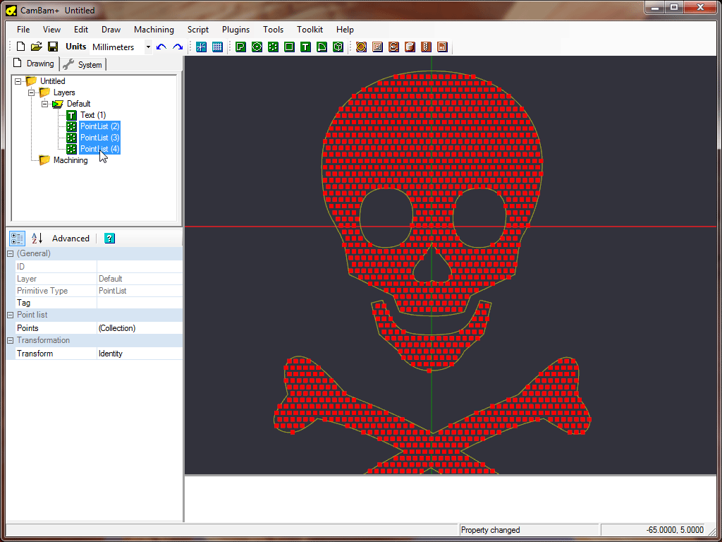
In a new CamBam drawing, insert a text object  .
The Wingdings capital ‘N’ character happens to be a natty jolly roger.
.
The Wingdings capital ‘N’ character happens to be a natty jolly roger.
Set the text

Step 2 - Fill text object with points
Select the text object then chose Draw - Points List - Offset Fill Geometry from the drawing context menu. This will prompt you for a step distance. Enter 2 here and press enter.
You should now have created a set of points which fill the selected geometry (excluding any holes in regions and text).
Step 3 - Insert a drilling machine operation
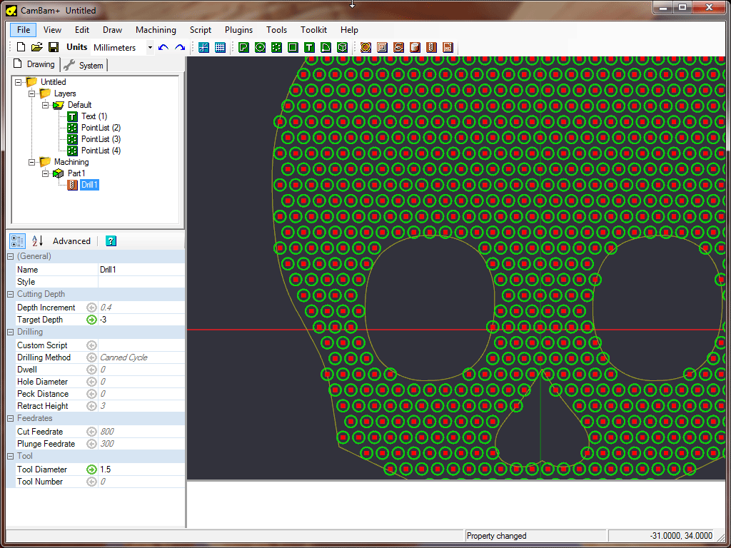
With the point lists selected, insert a drilling machine operation  .
.
Under the drill mop properties, set
That’s pretty much it! To make things clearer, you can right click on the Default layer in the file tree and select ‘hide’.
You should now just see a bunch of circles indicating the drilling hole sizes.
Right click on machining in the file tree to generate the gcode.
Here’s one I prepared earlier.
This is the aluminium cover off an ICY BOX external USB hdd enclosure. Should look neat with some LEDS behind it.

Most geometry can be used to generate point lists. Try experimenting with the other Draw - Point List options.