CAD Operations
Explode
Replaces a drawing object with its constituent parts.
For polylines, this will create individual line and arc objects.
For point lists, this will create individual point objects.
For text objects, each letter will be converted to a region.
For regions, the outer and inner shapes will be converted to polylines.
Join
This operation will attempt to join individual selected objects into single objects.
The join routine will first prompt for a join tolerance. This distance (measured in the current drawing’s units) is used to determine how close the end points of shapes need to be before they can be joined.
Offset
Creates a polyline, offset from the selected shape by a given distance.
If a positive offset distance is supplied, the resulting offset polyline will be outside the selected shape. If a negative offset is given, the offset polyline should be inside the shape.
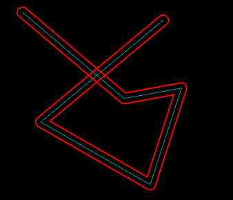
Open Offset
Creating an offset from an ‘open’ polyline will generate another open shape, offset from the original by the specified distance. Open Offset on the other hand will produce a closed shape that completely encloses the source shape.
Open offsets are particularly useful when drawing slot shapes, by drawing the center line of the slot then using the Open Offset operation. Another typical use is for drawing tracks to be used in PCB milling.
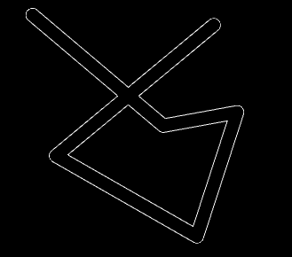
The image on the left shows the result of the Open Offset command used on an open polyline. Note that the closed polyline can loop back upon itself. On the right hand image, this open offset has been modified by using the Break at intersections operation, then the unwanted inner segments deleted.
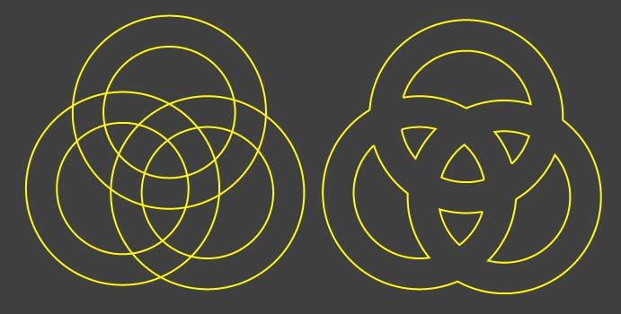
Union
Replaces shapes with the outer boundaries of all the selected shapes.
Subtract
Subtracts closed shapes from other closed shapes.
Intersection
Currently, this operation will only work on the first 2 selected objects.
Trim
Trims (deletes) parts of objects contained inside or outside selected trimming objects.
Fillet
Insert arc fillets of a specified radius into selected shapes.
Currently, fillets will only be inserted between adjacent straight (line) segments.
To create a fillet between distinct line segments, they must first be joined to form a single polyline.
Intersection Points
This operation inserts points at the intersections of selected shapes. This is useful when drawing, so that other drawing operations can ‘snap’ to these points.
Break At Intersections
Breaks selected shapes at the intersection points with other selected shapes.