Creating GCode
The basic work flow for creating Gcode files is:
- Create or Import drawing objects.
- Select drawing objects and define Machining Operations.
- Generate Toolpaths and visually inspect.
- Create the destination Gcode file.
Generating and Inspecting Toolpaths
Toolpaths are generated by selecting the Machining - Generate Toolpaths menu item, Pressing CTRL+T, or by right clicking on individual machining operations in the drawing tree and selecting Generate Toolpath from the context menu.
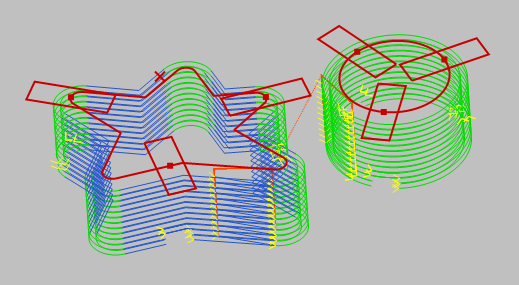
CamBam provides a 3D drawing view. Rotate the view (using ALT+Drag) to see more detail of the toolpaths including the different depth levels.
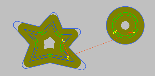
The toolpaths indicate the path that will be traveled by the central tip of the cutting tool. Different colors are used to differentiate straight line moves and arc moves. Small arrows indicate the cutting directions. Rapids are displayed using dotted red lines.
There are a number of settings which control the appearance of the toolpaths.
Toolpaths can be shown or hidden using the View - Show Toolpaths top menu and context menu options.
Other toolpath viewing options are available from the View menu.
Setting the drawing view option
Another useful setting is the
Select a post processor
A post processor will help covert machining operations and toolpaths into gcode, suitable for specific target machines.
If no post processor is defined, the default post processor is used.
Each drawing file can specify its own post processor, set in the machining options. To set a default post processor for all drawings, a default drawing template can be created which contains the required post processor.
See the post processor section for more details.
Creating Destination Gcode File
Once the machining operations have been correctly defined and inspected, a Gcode file can be produced to send to the CNC controller.
This is done by selecting the Machining - Produce Gcode menu option.
If a gcode file has not been previously created, a destination file location prompt is displayed.
The gcode filename is stored, and can be changed, by selecting the machining object in the drawing tree, then changing the
A default filename is suggested by appending the default Gcode file extension to the current filename. In the system configuration settings there is a setting called Default GCode Extension which is used to set the file extension.
Often it is useful to be able to create Gcode from a single machining operation. This is particularly useful for new designs, where each machining step can be exported and tested separately. To do this, right click a specific machining operation in the drawing tree and select Create Gcode File from the context menu.