Tutorial: 3D Profile
This tutorial gives an introduction to the 3D Profile operation, and covers:
- Loading 3D models, sizing and positioning.
- Front face waterline roughing.
- Front face scanline finishing.
Loading 3D models, sizing and positioning
Loading
CamBam can read .3DS file, .STL and .RAW 3D mesh files. These can be loaded using the File - Open menu option or by dragging files onto the CamBam drawing window.
If an imported object is not immediately visible, it may be because its default dimensions are very small compared to the currently display stock object. If this is the case, temporarily hide the stock using View - Show stock, then use View - Zoom to fit.
To machine successfully, the 3D model needs to be aligned within the intended machining area. This may involve combinations of the following transformations.
Sizing
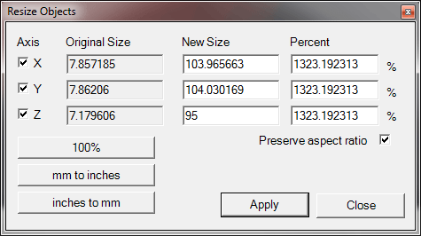
To make the model a fixed size, the Transform - Resize command can be used.
This will open the Resize window which will show the existing object dimensions and allow them to be resized to a specific
dimension, or by a scaling percent.
Rotating
The model should be rotated so that it is facing toward the screen (i.e. in the positive Z direction).
Transform - Rotate can be used to rotate selected objects. First select a rotation point, and then move the mouse around this point to select a rotation angle. Press the X, Y or Z keys to change the current axis of rotation. If snap to grid is enabled, the rotation angle will snap to multiples of 30 and 45 degrees.
Selected objects can also be rotated by using the transformation property editor.
Rotations follow a right hand rule, so to visualise this, point your right thumb in the direction of the positive axis of rotation.
A positive rotation is then in the direction that your fingers curl around the axis.
Another alternative is to use free-hand rotation. This is done by selecting objects, then holding the SHIFT key while using the view rotation key+mouse combination (ie ALT + left mouse drag or Center mouse + Left mouse drag, depending on your configuration settings).
Positioning
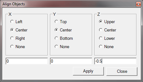
Transform - Align can be used to position selected objects. This will display a form with 3 columns, one for each axis. Select the point of the selected axis to align, or none to leave the current axis position intact. Enter the drawing coordinate underneath which will be the new location of the alignment point, then press Apply.
For example, to position an object so that it’s lower left corner is at the drawing origin and the highest Z point is just below the stock surface (if using Z=0), use the following alignment values:
X - Left, Value = 0
Y - Bottom, Value = 0
Z - Upper, Value = -0.5
It may be more convenient to reference the machine’s Z=0 to the work table, then use a
Z - Center, Value = 0

This image shows a 3D model loaded, sized and positioned
Front face waterline roughing
Waterline roughing is an efficient way to clear the bulk of the stock around the 3D model.
Create a 3D Profile operation
Select the 3D surfaces to machine, then insert a 3D Profile machining operation (Machining - 3D Profile)
or select the  icon from the toolbar.
If a Stock object has been correctly defined, some properties may be automatically calculated, such as
Basic Properties
Note: dimensions shown here are metric.
| Property | Value | Notes |
|---|---|---|
|
|
|
|
|
|
3 | The maximum Z depth per cut of each machining layer. |
|
|
3 degree |
As well as making life easier for the cutter, this also gives the Fast Plunge Height behaviour a reference point which helps avoid slow plunges. |
|
|
1 | Leave a small amount of stock to be cleared away in the finishing pass, to avoid waterline machining marks being visible. |
|
|
0 | In this example, Z=0 is referenced to the stock surface. |
|
|
-50 | If the model is 100 units tall, this will machine the top half of the model. |
|
|
6 | To increase roughing speed, use a larger tool. |
|
|
|
Scanline (horizontal /vertical) and waterline finishing methods will adjust tool paths for bull/ball nose cutters. For waterline roughing operations, the tool profile does not affect the tool path. |
Advanced Properties
| Property | Value | Notes |
|---|---|---|
|
|
0.5 | Distance between toolpaths expressed as a fraction (0-1) of cutter diameter. |
|
|
False |
CamBam's waterline routines have been designed to work best with natural / curved shapes. Engineering shapes with perpendicular sides
can potentially cause problems. If problems are encountered, setting |
General Settings
There are some properties under Machining that are useful when working with 3D files.
| Property | Value | Notes |
|---|---|---|
|
|
|
3D Toolpath generation can take many minutes. This option will prompt whether to regenerate toolpaths before creating gcode. If 'No' is specified, the post processor will use the last generated toolpaths. |
|
|
0.2 |
A small value here allows the post processor to rapid down to the fast plunge height distance above the last cut stock depth and can speed machining times considerably. Warning! Care should be taken with this setting, especially for machines with flex or backlash. Setting. |
|
|
|
Having front roughing, finishing and back face toolpaths visible is very confusing. This option will only
show the toolpaths for the machining operation currently selected in the drawing tree. |
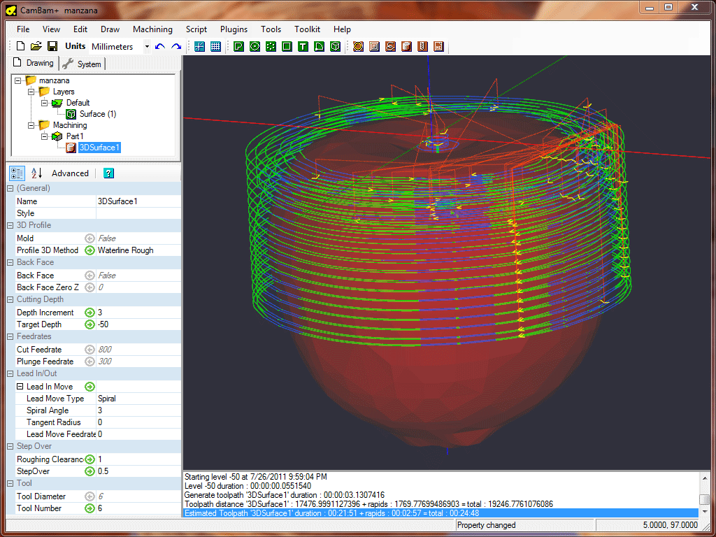
This image shows the waterline roughing toolpaths.

Simulation of the roughing pass in CutViewer Mill
Scanline finishing
Once the bulk of the material has been cleared by roughing, a scanline finishing pass can be applied. Select the 3D surface and insert a second 3D Profile operation.
This time, set the
Basic Properties
Note: dimensions shown here are metric.
| Property | Value | Notes |
|---|---|---|
|
|
or |
|
|
|
0 | Depth increment should be 0 to do a single finishing pass. |
|
|
-50 | Use the same target depth as the roughing pass. |
|
|
0 | No roughing clearance - will clear off clearance stock from the roughing pass. |
|
|
0.1 | Distance between toolpaths expressed as a fraction (0-1) of the cutter diameter. Smaller stepovers will give a nicer finish but take longer to machine. |
|
|
0.1 |
This is the distance along toolpaths expressed as a fraction (0-1) of the cutter diameter, at which the height of
the model is tested. 0.1 should be adequate, but a smaller value could be used if inaccuracies occur (especially around small features or perpendicular edges). |
|
|
3 | A smaller tool will result in more detail but takes longer to machine. |
|
|
|
The horizontal and vertical scanline, as well as waterline finish, methods will adjust tool paths for ball nose cutters. |
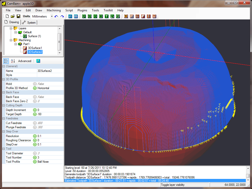
This image shows the scanline finishing toolpaths
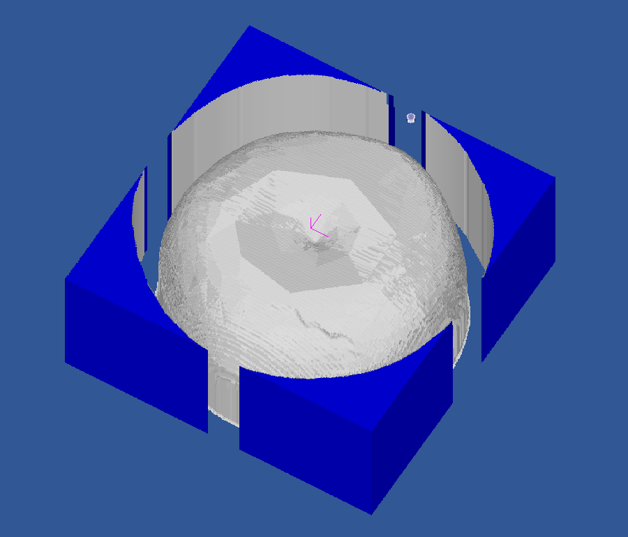
The finishing pass simulated in CutViewer Mill
Adjusting the machining boundary
The 3D profile operation will machine the minimum area around the objects. To change this behaviour, a number of boundary options can be defined.
| Property | Value | Notes |
|---|---|---|
|
|
2 | Adds a small extra margin around the shape outline boundary. |
|
|
3 | Tapers the boundary edge which helps give cutter clearance at lower depths. |
Back face machining
Please refer to the 3D Profile - back face tutorial.