 Profile Machining Operation
A 2.5D Profile machining operation is typically used to cut out shapes.
Other uses include facing edges and with increased cut widths can be used to create pockets.
Cuts can be inside or outside a selected shape.
Lead in moves and holding tabs are supported.
Properties
|
|
The clearance plane (offset from the work plane). The clearance plane should be clear of the stock and any holding devices to allow free movement to any location. |
|
|
Makes sure adjacent toolpaths do not overlap. Multiple Toolpaths are unioned together. |
|
[New 0.9.8] |
|
|
|
A multi-line gcode script that will be inserted into the gcode post after the current machining operation. |
|
|
A multi-line gcode script that will be inserted into the gcode post before the current machining operation. |
|
|
The feed rate to use when cutting. |
|
|
Controls whether to cut to depth first or all cuts on this level first. |
|
|
The total width of the cut. If this width is greater than the tool diameter, multiple parallel cuts are used. |
|
|
Depth increment of each machining pass. Determines the number of passes to reach the final target depth. |
|
|
|
|
|
The depth increment of the final machining pass. |
|
|
Defines holding tabs (bridges) to prevent cut parts moving while cutting. See the holding tab reference for more information. |
|
|
Controls whether to cut Inside or Outside the selected shapes. |
|
|
Defines the type of lead in move to use.
Refer to the lead move section for more information. |
|
[New! 0.9.8] |
Defines the type of lead out move to use. Refer to the lead move section for more information. |
|
|
Maximum distance as a fraction (0-1) of the tool diameter to cut in horizontal transitions. If the distance to the next toolpath exceeds MaxCrossoverDistance, a retract, rapid and plunge to the next position, via the clearance plane, is inserted. |
|
|
Controls the direction the cutter moves around the toolpath.
|
|
|
Each machine operation can be given a meaningful name or description. |
|
|
An option that controls how the toolpaths are ordered in gcode output.
|
|
|
The feed rate to use when plunging. |
|
|
List of drawing objects from which this machine operation is defined. |
|
|
Currently only supported by 3D Profile and Lathe machining operations. |
|
|
This is the amount of stock to leave after the final cut. Remaining stock is typically removed later in a finishing pass. Negative values can be used to oversize cuts. |
|
|
A composite property that enables the creation of pseudo 3D objects from 2D shapes by creating radii and slopes. See the side profiles reference for more information. |
|
|
The direction of rotation of the spindle. |
|
|
The pulley number or dial setting of the spindle for the target speed. |
|
|
The speed in RPM of the spindle. |
|
|
Used to select a point, near to where the first toolpath should begin machining. |
|
|
The cut is increased by this amount each step, expressed as a fraction (0-1) of the cutter diameter. |
|
|
The feed rate to use for crossover moves. |
|
|
This is the Z offset of the stock surface at which to start machining. |
|
[New! 0.9.8] |
Select a CAM Style for this machining operation. All default parameters will be inherited from this style. |
|
|
A general purpose, multi-line text field that can be used to store notes or parameter data. |
|
|
The Z coordinate of the final machining depth. |
|
|
This is the diameter of the current tool in drawing units. If the tool diameter is 0, the diameter from the tool information stored in the tool library for the given tool number will be used. |
|
|
The ToolNumber is used to identify the current tool. If ToolNumber changes between successive machine ops a toolchange instruction is created in gcode. ToolNumber=0 is a special case which will not issue a toolchange. The tool number is also used to look up tool information in the current tool library. The tool library is specified in the containing Part, or if this is not present in the Machining folder level. If no tool library is defined the Default-(units) tool library is assumed. |
|
|
The shape of the cutter If the tool profile is Unspecified, the profile from the tool information stored in the tool library for the given tool number will be used.
|
|
|
Used to transform the toolpath. Warning! This property is experimental and may give unpredictable results.
|
|
|
Instructs the gcode interpreter whether or to use look ahead smoothing.
|
|
|
Used to define the gcode workplane. Arc moves are defined within this plane. |
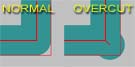 Set CornerOvercut to True to add an extra machining move, which will cut into inside corners that would not ordinarily be cut.
This will result in some stock overcutting but is useful in cases where machined parts
will be fitted together such as slot joints or inlays.
Set CornerOvercut to True to add an extra machining move, which will cut into inside corners that would not ordinarily be cut.
This will result in some stock overcutting but is useful in cases where machined parts
will be fitted together such as slot joints or inlays.