CAD Transformations
Moving
Objects can be moved by selecting them, then holding down the SHIFT key whilst dragging the objects with the mouse.
Using the keyboard only, selected objects can be moved holding the SHIFT key and using the arrow keys. This will move the object one minor grid unit in the arrow key direction (If using millimeters, this will be 1mm, if using inches then this will be 1/16"). If CTRL+SHIFT keys are held down, objects will be moved one major grid unit (If using millimeters, this will be 10mm, if using inches then this will be 1")
NOTE: The grid major and minor units can be defined in the system configuration, grid section.
Alternatively, the Transform - Move menu option can be used to position an object by first selecting a source point, then a destination point. This can be useful to accurately position one object relative to another, as the point selection will ‘snap’ to object points.
Three point Edit - Move New! [V1.0]
The Edit - Move command now supports up to 3 source and destination points.
Hold down the CTRL key and click to select up to 3 source points.
If only one point is selected, the move operation works as before by selecting the target destination point.
If two source points are selected, the first destination point will be the new location for the first point. The second destination point will form a line on which the moved second point lies. This in effect allows a move and a rotation in the XY plane in one operation.
If three source points are selected, the first destination point will be the new location for the first point. The second destination point will form a line on which the moved second point lies. The third destination point will form a plane on which the moved third point lies. This allows a shape to be moved in three dimensions. For example a 3D mesh could be aligned to a mounting plate by selecting three matching reference points at the center of three bolt holes.
The selected points are color coded: Red, Green, Blue to identify the current selection point.
Resizing
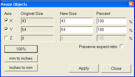
The Transform - Resize menu option (or Ctrl+E) is used to resize selected drawing objects.

Each axis can be scaled separately by using the check box to the left of the axis label. Unticked axis will retain their original size.
The
A specific size can be entered in the
If the
Short cut buttons are provided for common scaling factors
- 100% will restore the objects their original size (100%).
- mm to inches will scale mm measurements to inches.
- inches to mm will scale inch measurements to millimeters.
Press Apply for the resize to take effect.
Rotating
The Transform - Rotate menu option (or Ctrl+R) is used to rotate selected objects.
This will first prompt for the center point of rotation.
Next, a reference (or start) angle is prompted. This can be useful when rotating a shape a set angle from a given edge. For example, to draw a perpendicular to an edge, draw a line along the edge, select the rotation center at one end of the line and the reference angle at the other line end point; then rotate 90 degrees using the angle snaps.
Pressing the middle mouse button will skip the reference angle selection and will use a 0 degrees reference, where 0 degrees is along the positive X axis.
Move the mouse about the rotation center point to control the rotation angle.
If the View - Snap to grid menu option is enabled, the rotation angle will snap to common angles (multiples of 30 and 45 degrees).
The rotation command can also be used to rotate about other axis. Pressing the X, Y or Z keys while rotating will select the axis of rotation. The angle of rotation is always set by moving the mouse around the center point in the plane of the drawing view, regardless of the axis setting.
Rotate can also be used to mirror an object, by selecting the Y axis of rotation, and rotating 180 degrees.
Selected objects can also be rotated ‘freehand’, by selecting them, holding down the SHIFT key,
then using the view rotation mouse+keyboard combinations. For example, ALT+SHIFT and mouse drag.
This method currently only rotates about the origin and does not snap to angles, so is only really useful for
positioning 3D objects for artistic effects.
Align
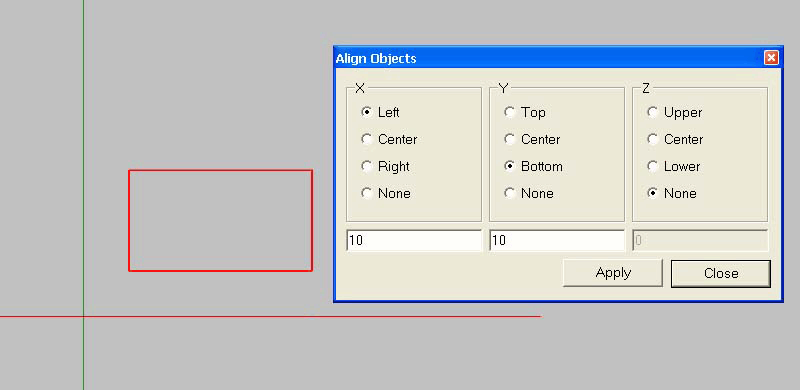
Transform - Align can be used to position selected objects. This will display a form with 3 columns, one for each axis. Select the point of the selected axis to align, or none to leave the current axis position intact. Enter the drawing coordinate underneath which will be the new location of the alignment point, then press Apply.

In this above example, the left most side of the rectangle is aligned to X=10 and the bottom part of the rectangle is aligned to Y=10. The Z location of the rectangle will remain unchanged.
Mirror
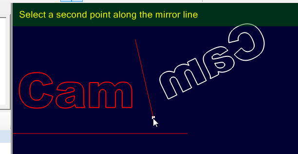
Creates a mirror copy of all selected drawing objects about a mirror line. The mirror line is specified by selecting two points along the line.
The Shift key can be used to constrain the reflection plane according to the current angles (0, 30, 45, 60 and 90 ° for each quadrant)

Array Copy
Array copy is used to create multiple copies of a drawing object, with each copy offset a specified distance.
First select the objects to copy, then select the Transform - Array Copy menu option. The routine first prompts for the number of copies to make, not including the original selected objects.
The routine then prompts for an offset distance for each copy, in the format X,Y,Z. The Z coordinate can be omitted and 0 will be assumed.
There is also an optional 4th parameter ‘scale’, which can be used to increase (scale > 1) or decrease (scale < 1)
the size of each copy. Each copy is scaled using the following formula 1+(scale-1)*n, where n is the copy number.
For example 0,1,0,0.9 would offset each copy 1 unit in the Y direction and scale the copies 90%, 80%, 70%,etc of the original size.
Polar Array Copy
Polar array copy is used to create multiple copies of a drawing object around a point, with each copy offset by specified angle.
First select the objects to copy, then select the Transform - Polar Array Copy menu option. The routine first prompts for the center point of rotation, followed by the number of copies to make, not including the original selected objects.
The routine then prompts for an offset angle for each copy, about each axis, in the format X,Y,Z. The Z rotation coordinate can be omitted and 0 will be assumed. The angles are measured in degrees.
Rotation follows the right hand rule. To visualise this, with your right thumb pointing in the direction of the positive axis, the direction of rotation for a positive angle is the direction that the other fingers curl.
For example, to make 12 objects, evenly spaced around a point, set the number of copies to 11 (note the original copy is not counted), and use the following rotation value : 0,0,30 (that is 30 degrees around the positive Z axis).
Centring
The Transform - Center menu options can be used to center objects about the drawing origin.
There are two variations:
Center (Extents) will use the center point of the bounding rectangle to align the selected shapes.
Center (Of Points) will align the ‘average’ point of all the control points contained in the selected shapes.
Transform matrix
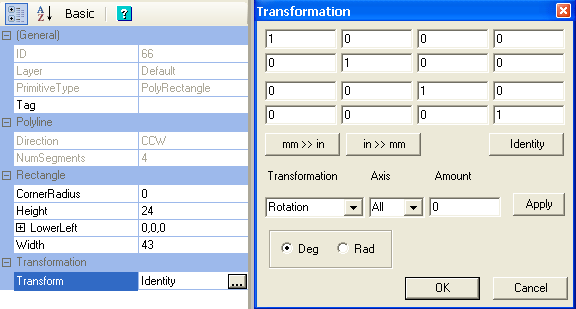
More advanced transformations can be defined by changing the selected object’s
The transform property is located in the object property window for the selected objects(s).
Click the […] button to the right of the

Values can be entered into the matrix directly or a number of helper buttons can be used.
To rotate, scale or translate, select the required operation from the Transformation drop down list, select an Axis that the transformation applies to and an amount, then press the Apply button.
For rotations, the positive Z axis is coming out of the screen towards you.
If you place your right thumb in the positive Z direction, your fingers will curl in the direction of a positive rotation about the Z axis.
This right hand rule applies to rotations about all the axis.
Multiple transformations can be applied as along as Apply is clicked between each.
To reset the transformation matrix, click Identity.
Apply Transformations
Changing the Transform property does not initially change any other object properties. For example, a circle center point and diameter, or polyline control points will remain unchanged. The transformed values will be automatically calculated when needed (during toolpath generation for example). To change these properties immediately, select an object then use the View - Apply Transformations menu option. This will transform all the shape’s properties where appropriate and then reset the transform matrix back to Identity.
Note: As of version 0.9.8 many operations will now automatically apply transformations. This behaviour can be controlled by changing the Auto Apply Transformations in the system configuration.