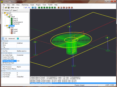
Simple Example (Stepper Mount)
This sample project will demonstrate the general process involved in going from a new drawing to final gcode. The object is a mounting plate for a Nema 23 stepper motor and will include CAD, pockets and drilling machine operations.
The basic work flow for generating CAM files in CamBam is to first draw or load in drawing objects, then insert machining operations based on these geometric objects and finally generate gcode files.
Download the files used in this tutorial
Step 1 - Create and set up a new drawing.
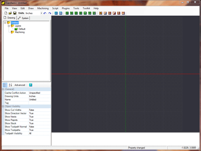
Start with a empty drawing, use File - New or the new file icon  {.icenter} from the toolbar.
In this example we are going to work in Inches, so the first step is to select the drawing units from the toolbar. 
This will prompt :
“Would you like to change the default units to Inches?”
This question refers to the global drawing units property that is set
in the system configuration settings.
The global units option is used to set the drawing units for new drawings.
Select Yes to update the global setting as well as the current drawing.
Selecting No will change the current drawing to
Show the drawing grid and axis by selecting the Show Axis  and Show Grid
  buttons from the toolbar.
To zoom the image so that it fills the screen and makes it central, select View - Zoom Actual Size from the main menu
Step 2 - Drawing circles
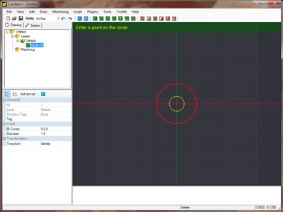
We will draw a circle to define the raised circular area around the stepper shaft. This circle will later be used to form a circular pocket. For a Nema 23 stepper motor, this area is around 1.5” (38.1mm) diameter. We will also draw a circle to denote the shaft clearance hole with diameter 0.5” (12.7mm).
Select the circle drawing tool button  from the tool bar.
A prompt will be displayed at the top of the drawing window to guide the current drawing operation.
Select the center point for the circle on the drawing origin (0,0). If snap to grid is not turned on, right click the drawing to display the drawing context menu, then click View - Snap to Grid.
Next, select another point on the circle. Chose the point (0.75,0). The point coordinates can be seen on the bottom right of the lower status bar. If the current grid settings will not allow selecting an exact point, chose a point nearby then the circle diameter can be modified later.
A circle drawing object will now appear in the drawing tree on the left. The properties for this circle will be displayed in the
object properties window on the lower left. The
These values can be modified in the object properties window if required.
Insert a second circle with center the origin and make the diameter 0.5.
Step 3 - Drawing a rectangle and making it central
The rectangular body of a Nema 23 stepper is about 2.36” (60mm). We will make our mounting plate 5” (127mm) wide and 2.375” (60.3mm) tall.
Select the rectangle drawing tool button  from the tool bar.
Once again, a prompt will be displayed at the top of the drawing window to guide the current drawing operation.
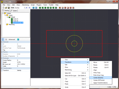
To simplify drawing, we will draw the rectangle with the lower left corner on the origin then center it. Click the origin for the lower left point then the point (5,2.375). Again, if the exact coordinates can not be selected then don’t worry as these can be edited under the rectangle object’s properties.
Hint: To pan the drawing view, click and drag the drawing with the center mouse button.
The arrow keyboard keys can also be used to pan the display.
To zoom the display, scroll with the mouse wheel.
A rectangle object should appear in the drawing tree and it’s properties will be displayed in the object property window.
Change the
To center the rectangle, first make sure it is selected (it will be highlighted in bold red), then right click the drawing window and select Edit - Transform - Center (Extents) from the context window.
Step 4 - Inserting 4 points for mounting hole positions
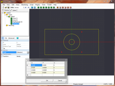
The Nema 23 stepper motor has 4 bolt holes arranged in a square 1.856” (47.14mm) apart. We will be adding a drilling machining operation later to generate these holes so to prepare for that we need to insert 4 center points at the hole centers.
There are a number of ways to achieve this but here are a couple of options.
Select the point list tool button  from the tool bar.
Click 4 points around the origin with the following coordinates :
( 0.928, 0.928 ), ( 0.928, -0.928 ), ( -0.928, -0.928 ), ( -0.928, 0.928 )
Press the Enter key or click the middle mouse button to finish drawing the point list.
A PointList object will have been created in the drawing tree and it’s properties will be visible in the object property window.
There is a property called
An alternative way to achieve this is to first draw another rectangle with the lower left point on the origin then change the rectangles height and width
properties to both be 1.856. Select the rectangle and center it (Right click, Edit - Transform - Center (Extents) ).
Now draw a point list  as before.
This time the drawing points should snap to the rectangles corner points.
It may be easier to turn off Snap to grid and make sure Snap to objects is turned on. Both these are set in the right click, View menu.
Once the points are drawn, the guide rectangle can be selected then deleted.
The geometry for the stepper plate is now complete, so now would be a good time to make sure the drawing is saved.
Step 5 - Inserting a pocket and viewing the toolpath
Select the large circle drawing object then click the pocket machining operation button
 from the toolbar.
A new pocket object will be created and displayed under the Machining folder in the drawing tree.
The object property window will display the pocket’s properties ready for editing.
CamBam will initially show only a limited number of common properties for the selected machining operation. Clicking the Advanced button at the top of the property grid will show the complete list of available properties.
For this example we are going to use a 0.125” (3.175mm) carbide cutter and cut at a feed rate of 7ipm (~180mm/min). The plunge feedrate will be 2ipm (~50mm/min) and a maximum of 0.02” (0.5mm) depth of material will be removed during any pass.
Change the pocket machine operation’s properties to the following:
| 0.125 | |
| 0 | |
| 0.02 | |
| -0.064 | |
| 7 | |
| 2 | |
| 0.1 |
Note: The
Target Depth value sets the final depth of the pocket and is the Z coordinate (relative to the origin) of the bottom of the finished pocket. CamBam assumes positive Z values are up, away from the stock and negative Z values are moving down into the stock or work table. If you try to enter aTarget Depth above the stock surface the program will report a warning in the message window and set the target depth to the same as the stock surface.
To generate the resulting toolpath for the pocket, right click the drawing to bring up the drawing context menu, then select
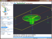
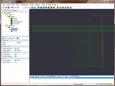
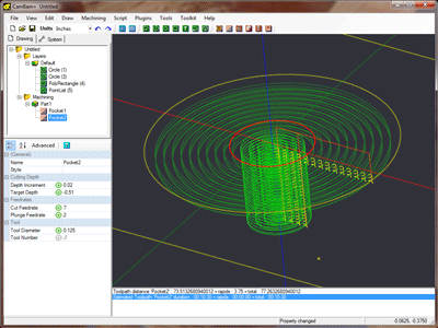
Machining - Generate Toolpaths. This will display green circles indicating the path of the center point of the cutting tool.
Arc toolpaths are displayed in green, straight lines in blue.
To view the toolpath side on, select View - XZ Plane. This shows 4 cutting levels. The X axis indicated by the red line is the
level of the stock surface. The distance between each level is set in
To rotate the 3D drawing view, hold the ALT key then click and drag on the drawing. To reset the view, hold the ALT key then double click the drawing. Other rotation modes can be set in the Rotation Mode setting of the system configuration.
Now we will insert a second pocket to cut the shaft clearance hole. Select the inner circle and insert a second profile machine operation.
This time use the following properties:
| 0.125 | |
| -0.064 | |
| 0.02 | |
| -0.51 | |
| 7 | |
| 2 | |
| 0.1 |
Step 6 - Insert drilling machine operations
Select the point list object that defines the bolt holes, then click the drilling operation button
 from the toolbar.
If you have trouble selecting the points from the drawing, you can also select them from the drawing tree view.
CamBam supports 3 different drilling methods:
Canned Cycles, which use gcode canned cycles G81, G82, G83 at each drilling point.
Spiral Milling, defines a spiral toolpath that cuts evenly through stock using a milling cutter and can cut a hole larger than the cutter diameter at arbitrary sizes.
Custom Scripts, which allow snippets of gcode to be inserted at each drill point.
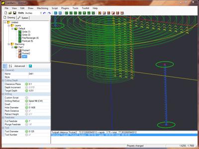
This example will drill 4 x 0.1406” (~3.6mm) that will then be tapped to accept a machine screw. The 0.125” cutter should still be in the CNC machine following the pocket so we will use spiral mill drill option to the correct hole diameter.
Change the drilling machine operation’s properties to the following:
| 0.125 | |
| 0 | |
| -0.51 | |
| 7 | |
| 4 | |
| 0.1 | |
| SpiralMill_CW | |
| 0.1406 |
Generate the toolpaths again to view the resulting spiral paths.
Step 7 - Creating GCode
Before producing the gcode output, now would be a good time to save your drawing.
Then visually inspect the toolpaths and double check the parameters of each machining operations.
To create a gcode file (or post), right click to get the drawing menu then select Machining - Produce GCode.
CamBam will then prompt for the location of the gcode file to produce. If the drawing file has been saved, the default file will be in the same folder as the drawing file with a .nc extension.
If the destination file already exists you will next be asked to confirm whether to overwrite it.
To control how the gcode file is produced, select the machining folder from the drawing tree. The machining properties for this drawing will then be displayed in the object properties window.
For NIST RS274 compatible interpreters such as LinuxCNC, Mach3 and USBCNC the default machining properties should be fine.
One setting to check is the
