Holding Tabs
Holding tabs or bridges are used to hold material in place when cutting through the entire thickness of stock. They are formed by breaking or bending the toolpaths at the lower depths of the cut, to leave areas of stock intact.
The Profile machining operation contains a
The quickest way to enable holding tabs is to select the profile machining operation in the drawing tree.
Then right click the drawing window to open the drawing context menu.
At the bottom of the context menu, a Holding Tabs sub menu is displayed. From here, select Autocalc.
This is similar to setting the holding tab

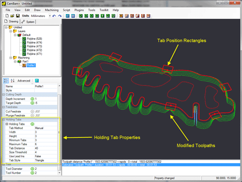
The holding tabs will be displayed as a series of rectangles spaced around the source drawing shapes.
If the automatically generated holding tabs are in inconvenient positions, they can be quickly moved by clicking
and dragging them to an alternate position. This will also change the
If a tab is displayed with a red cross marker through it, this indicates a holding tab that cannot be applied to any toolpaths. This is often caused when holding tabs are positioned on the corners of shapes. In these cases, manually adjusting the tab position will resolve the problem. The X marker will not be cleared until the toolpaths are regenerated.
When a profile machining operation is selected, the drawing context menu can also be used to Add and Remove holding tabs. When removing tabs, right click the mouse within the rectangle of the holding tab to remove. Similarly, when adding tabs, first right click on the source shape where the new shape should be located, then select Add Tab from the resulting Holding Tabs context menu.
The number and spacing of the automatically generated holding tabs is controlled by the
If
The
The size of the holding tabs is controlled by the
Experience will dictate the optimum tab height and widths. Too large tabs will hold parts securely but require extra manual cleanup to remove the tab stock. Too small tabs run the risk of the parts breaking free, which can damage both parts and cutting tools. The type of material will also affect this choice. Metals typically can use smaller holding tabs while woods and plastics will need wider or thicker tabs to compensate for the brittle nature of the material.
There are two types of holding tab cross-section shapes available which is defined in the

Properties
|
|
The height of the holding tab measured from the stock base or target depth. |
|
|
The maximum number of auto tabs to insert around each shape. |
|
|
The minimum number of auto tabs to insert around each shape. |
|
[New! 0.9.8] |
Shapes with perimeters less than this value will not have any automatically calculated tabs. |
|
|
The approximate distance between each automatically generated holding tab. |
|
|
|
|
[New! 0.9.8] |
[New! 0.9.8N] |
|
|
Square holding tabs will result in a vertical plunge on the trailing edge. This can be hard on cutters, especially
in harder materials. If |
|
|
The final width of the holding tab, measured at the thinnest part of the tab. |
Advanced Settings

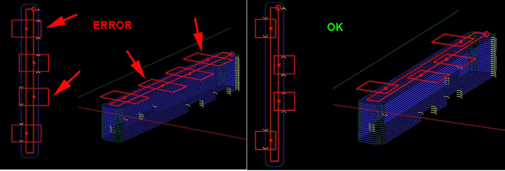
In some cases, such as very narrow source shapes, a problem can occur where the shape of the holding tab may extend to the toolpath on the other side of the part and holding tabs incorrectly assigned to the wrong side.
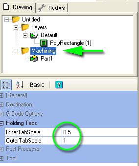
To help resolve this problem, two parameters are available in the Machining properties of the drawing:
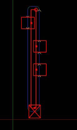
The following image show a narrow source shape that has caused an incorrect holding tab. Reducing the inner tab scale resolves this problem.

