Tutorial: 3D Profile - back face machining
This tutorial explains some more advanced concepts of the 3D profiling operation and covers:
- Back face machining.
- 3D Holding Tabs.
Back face machining.
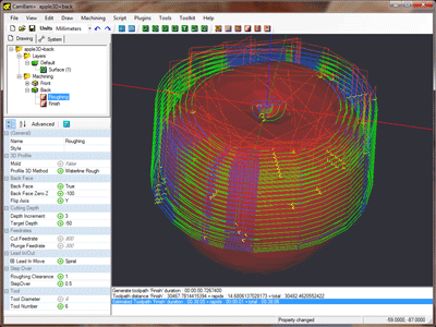
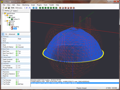
Back face machining is very similar to the front face roughing and finishing passes, with a few extra parameters to control the back face machining behaviour.
The front and back faces may be machined in a single piece of stock, by flipping the stock over after the font face has been machined. Alternatively the front and back faces may be machined in separate pieces of stock which can then be fixed together.
The Back Face Zero Z parameter is a key concept to understand. The 3D model is in effect, flipped over to machine the reverse side. Back Face Zero Z determines the current Z coordinate that will become Z=0 when the model is flipped.
Referencing Z=0 to the machine’s work surface and setting a positive stock surface value will result in the model being rotated about Z=0. In this case Back Face Zero Z should be set to 0.
If the top of the stock is referenced as the machine Z=0,
Basic Properties
Hint: If a Part has already been created containing the roughing and finishing passes for the front face, creating the back face can be simplified by copying and pasting the Part used by the front face and then altering the properties specific to back face machining.
| Property | Value | Notes |
|---|---|---|
|
|
|
|
|
|
0 |
In this example, the table surface Z=0 is used, so the model is rotated about Z=0 to machine the back face. |
| -100 |
In this example, the stock surface Z=0 is used, the model is around 100 units tall and is aligned so that the highest Z point is at or just below the stock surface (Z=0). |
|
|
|
|
The stock will be rotated around the X axis (top to bottom), when the back face is to be machined. |
|
|
The stock will be rotated around the Y axis (left to right), when the back face is to be machined. |
The back face toolpaths will be displayed in the orientation they will be machined, which may overlay the top face of the surface.
Hiding the drawing layer containing the 3D surface, or setting wireframe view mode makes viewing the toolpaths easier.
3D Holding Tabs.
There is currently no automatic 3D holding tabs functionality, but this feature is planned for a future release.
Here is a method to manually create 3D holding tabs or sprues using cylinder meshes.
Extrude a circle
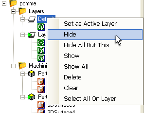 Hide the drawing layer containing the 3D mesh.
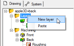
Create a new layer to contain the holding cylinders (‘tabs’).
Draw a 2D circle with a diameter of the holding tabs to be used. Place the center of the circle at the drawing origin (0,0).
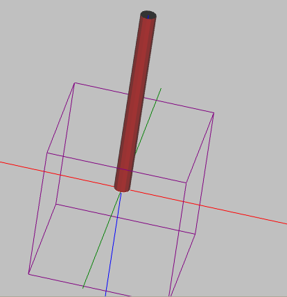
With the circle selected, select Draw - Surface - Extrude. Enter an extrusion height large enough to span the largest width
of the model plus an extra margin to allow for tool diameters.
You will also be prompted for the Arc Expand Tolerance. Curves will be converted to flat facets when extruding. This tolerance setting
controls how much error or deviation is allowed from the curve (measured in drawing units).
Rotating the drawing view should show a 3D cylinder extending in the positive Z direction.
Position the cylinder
First, center the cylinder (Transform - Center (Extents)).
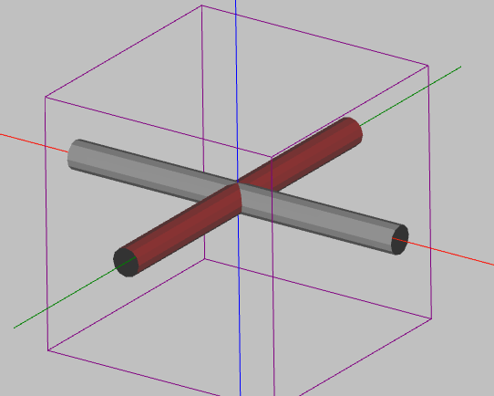
Use a combination of cut and paste and transformation rotations to position the cylinders at required positions around the model.
Adjust the machining boundary
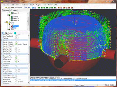
The holding tab shapes need to be added to the 3D profiles list of surfaces to machine. To do this, right click on the machining operation in the drawing tree and select Select Drawing Objects. Ctrl+click to select the extruded cylinders.
To prevent the machining operation machining around the ends of the cylinders, we need to reduce the boundary shape.
This is achieved by specifying
| Property | Value | Notes |
|---|---|---|
|
|
|
This will create a trimming boundary just from selected shapes. |
|
|
1 |
Enter the ID of the main 3D surface to machine, excluding any holding cylinders. |
