Machining Operations
A machining operation is an object that will generate toolpaths and machining instructions used by a CNC machine. Typically these operations will be based on one or more drawing objects.
CamBam provides the following machining operation types:
 Profile
This is a versatile 2D machining operation, typically used to cut around the inside or outside of a shape.
Profiles support holding tabs (sometime called bridges), which will hold parts in place once the full depth of the stock is cut through.
Lead in and Lead out moves can be added to reduce the stresses on parts and tooling and
the Side Profile property can be used to give 3D contours to the profile cut.
 Pocket
Pockets are used to clear out stock within selected shape outlines. Pockets will detect selected islands, or closed shapes within other shapes to form more complex shapes. This can be used to create raised lettering effects such as on a name plate.
 Drill
Drill
The drill operation is typically used to drill holes at selected point lists or circle centers using drill tooling. End mills can also be used to spiral mill holes larger than the tool diameter and complicated operations can be achieved using custom drilling scripts.
 Engrave
Engraving operations are used to machine over selected lines. As well as 2D geometry in the XY plane, they can also be used to follow 3D lines with varying Z heights such as in bitmap heightmaps.
 3D Profile
This operation is used to machine 3D shapes from surface mesh objects such as those imported from STL and 3DS files.
A number of different 3D methods are supported including waterline and scan-line methods with roughing and finishing options.
Front and back face operations are provided as well as creating inverted 3D machining operations for molds.
 Lathe
Lathe
The turning operation is a new, experimental featured introduced with CamBam version 0.9.8. This can create roughing and finishing operations based on 2D profile lines drawn in the XY plane, but machined in the conventional lathe XZ plane.
 NC File
The NC File operation is different to the other operations in that it is not based upon drawing objects, but can be used to include gcode from an external text file. This operation can also be used to display a toolpath or back plot gcode files. The contents of external gcode files will be included in the gcode output of the current CamBam drawing.
Inserting a machining operation
To add a machining operation, select one or more drawing objects (2D or 3D depending on the type of operation to be inserted), then click on the toolbar icon that corresponds to the desired operation, or choose from the Machining menu.
Machining operations can also be created by copying and pasting existing ones. Copies can be made from machining operations in the current file or from another file loaded in a second running instance of CamBam.
The new operation will appear in the drawing tree, within the currently active Part, and its properties will be available to modify in the property window below the tree view.
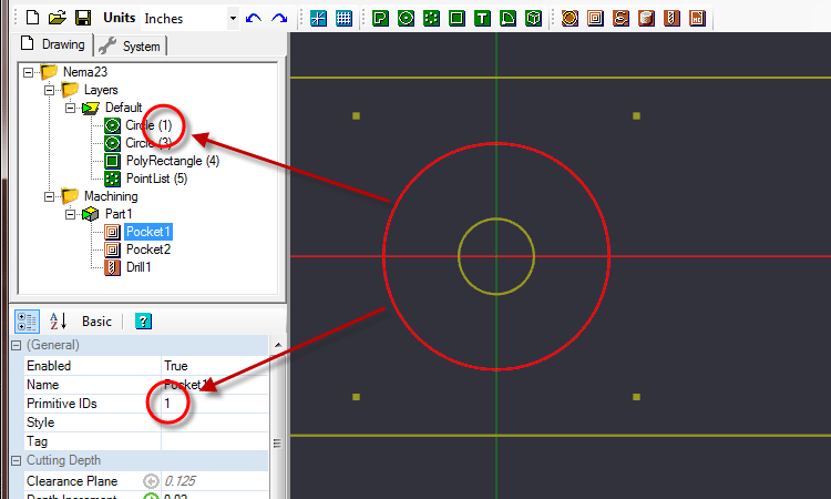
When machining operations are selected in the drawing tree, all visible drawing objects associated with the operation will be highlighted in the drawing view.
The list of unique IDs identifying the drawing objects associated with the operation can be found in the
Note: The
Primitive IDs property is only displayed in the Advanced property view.
Changing machining operation source objects.
It may be necessary to change the drawing objects associated with a machining operation if:
- Additional objects need to be added to the operation.
- A drawing object has been modified and its ID no longer matches that currently linked to the machining operation (for example, after converting a rectangle to a polyline for editing, its ID number will be changed).
- A machining operation has been created by copying an existing operation and new drawing objects need to be assigned.
To change the assignment of source objects of a machining operation:
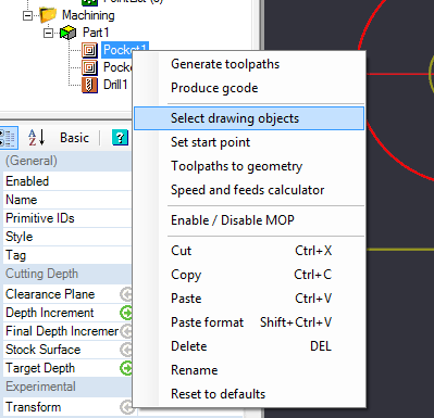
Click the right mouse button on the operation concerned to display the context menu for that operation, then use the Select Drawing Objects command.
The drawing window displays the objects already assigned to the operation in red. All the object selection methods can be used to alter the current selection. Holding the Ctrl key and left clicking objects will add and remove objects from the selection.
Clicking an empty area of the drawing will deselect all.
When finished, click the middle mouse button or press the Enter key to apply the selection.
Press the Escape key to abort the selection and revert to the original.
Pressing the [...] button to the right of the
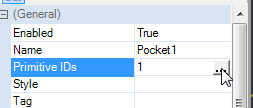
The
Managing machining operations
Right clicking a machining operation invokes a context menu with the following options.
Enable / Disable MOP: Activates or deactivates a machining operation. When disabled, the operation will appear greyed out, its toolpaths will be hidden and it will not be taken into account when creating the Gcode.
Set start point: Sets the starting point of a machining operation by clicking on the drawing at the desired start point. The operation will start at the closest point possible to the select start point.
This starting point will be indicated by a red circle which can then be moved by dragging with the mouse.
The coordinates of the chosen starting point will also be displayed, and can be edited directly, in the
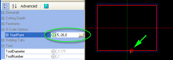
Selecting the  button to the right of the
Cut / Copy / Paste: Uses standard clipboard routines to manage the machining operations. These functions allow copies of the selected machining operations to be made in the current drawing, or in a different drawing loaded in another running instance of CamBam.
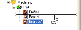
Machining operations may be reordered or moved between Parts by dragging them within the drawing tree. A horizontal bar indicates where the operation will be inserted.
Paste format: This function copies most of the properties of a machining operation that has been copied to the clipboard using the Copy command, into the selected target machining operation. The target’s name and source drawing objects are left intact.
Paste format can also be used to copy the contents of a machining operation into a CAM Style object.
Delete: Removes the selected machining operation.
Rename: Renames the selected machining operation.
.png)
Reset to defaults: All the properties of the machining operation will be set to Default so that they will inherit their values from the parent CAM Style.
If no style is specified for the machining operation, the Style set in the containing Part object will be used. If the Part does not have a defined Style, the Style set against the Machining object will be used. In the event that no style is defined at any of these levels, the default style will be used for the source of the Default values.
Note: The default style is the style with an empty name in the style library.
Warning: The default styles are very important for CamBam to function correctly and should not be renamed or removed.
Refer to the section on styles for more information.
Generate toolpaths: Calculate and display the tool paths for the selected machining operation only.
Produce Gcode: Creates the Gcode for this operation only, the suggested file name will be composed as follows.
Drawing name.part name.[machining operation].nc
See creating gcode section for more information.
Toolpaths to geometry: This feature allows you to create drawing objects from machining operation tool paths. These polylines can then be edited, used to create other toolpaths or exported as DXF.