Tutorial: Pocketing and Island Pocketing
This tutorial will describe using the Pocket machining operation and will also cover - Loading DXF files, CAD drawing, object transformations and Automatic Island Pockets.
Download the files used in this tutorial
Step 1 - Load a DXF file
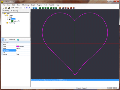
The sample file above, includes a heart shape DXF file. If you are married and fanatical about CNC, this shape can come in very handy indeed!
This shape is a nice and clean, closed polyline. If your DXF files contain many small segments or uses non polyline objects you should tidy the drawing before creating any machining operations.
To convert objects to polylines, select them, then select Convert To - Polyline from the drawing’s context menu, or when the drawing window has focus, use the CTRL+P shortcut key.
Step 2- Free hand CAD drawing
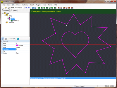
Use the polyline drawing tool  to draw a random shape around the heart.
This will form the outer boundaries of an island pocket.
For the last point, press the C key to close the shape, or click on the first polyline point
(the cursor should snap to it), then press ENTER or click the middle mouse button.
If the polyline does not sit evenly around the heart, you can free hand move objects by selecting them, then hold the SHIFT key and drag objects with the left mouse button. To position objects more accurately, use the Transform - Translate drawing context menu. This will translate an object given an origin and destination point.
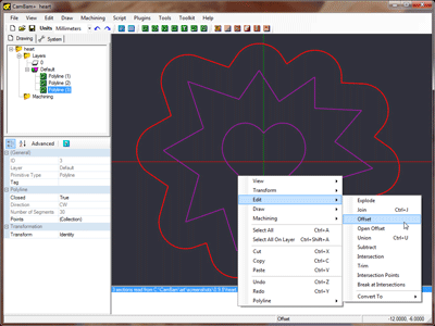
To make the shape a bit rounded create an offset shape. Select the polyline, then click Edit - Offset from the drawing context menu. This will prompt for a distance to draw an offset polyline. Positive offsets will be outside the polyline shape and negative offsets will be inside.
To rotate a shape, select it then use the Edit - Transform - Rotate menu option or CTRL+R keyboard short cut to enter rotation mode. Select a center of rotation point, a starting angle then move the mouse around the start point to the desired position.
Step 3 - Pocket the heart
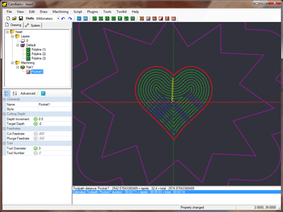
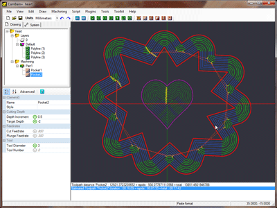
Select the heart shape then insert a pocket machine operation using the pocket tool  .
For pocketing basics, please see the Stepper Mount tutorial in Getting Started.
The important thing to remember is that the
CamBam can cut deep pockets by generating toolpaths at progressively deeper cutting levels.
The distance between each cut level is specified in the
To ensure a final light finishing pass at the lowest level cut, enter a small value in the
Another useful parameter is
If a negative
Step 4 - Creating an Island Pocket
Island pockets can be created automatically by selecting inner and outer polylines then inserting a pocket as usual. Shapes within other shapes will be detected and toolpaths will be excluded from these inner ‘hole’ shapes.
If there are 3 concentric shapes selected for a pocket, the pocketing routines will interpret this as a pocket within an island within a pocket. In this tutorial we could have used just 1 pocket from all 3 polylines, but for clarity 2 separate pockets were used.
With the 2 outer polylines selected, insert another pocket  .
.
To save entering in all the pocketing parameters for the second pocket, right click the first pocket operation in the drawing tree then select Copy from the context menu, then right click the second pocket operation and select Paste Format from the context menu. This will copy all the properties from the source operation into the destination, apart from information such as the operation’s name and lists of source objects.
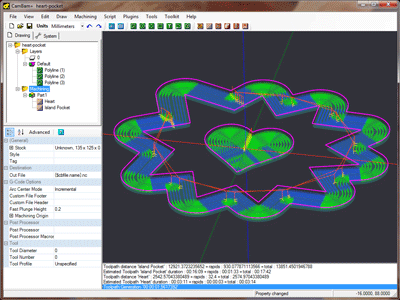
Generate the toolpaths again. If all is well, the routines should detect that you intend to do a island pocket and will generate toolpaths in between the 2 curves.
Step 5 - Show Cut Widths
Before we continue, we will turn on the Show Cut Widths option to indicate the areas that will be machined. From the main View menu, or the View sub menu of the context menu shown when right clicking the drawing, tick the Show cut widths option, if it is not already ticked.
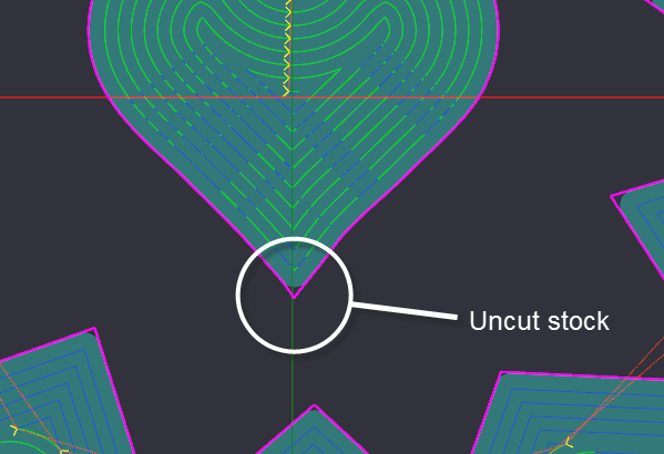
Show cut widths will shade the areas that will be cut. It should be easy to spot any areas that are not shaded and will therefore have stock remaining.
In the image below there will be uncut stock in the inside corner shapes where the tool radius cannot reach without overcutting.
Step 6 - Machine operation renaming.
The drawing is basically complete and ready to save and generate gcode, but first we will do some cosmetic changes to help manage the drawing.
Machine operations can be given a more meaningful name, to help with readability and debugging. To rename a machine operation, select it in the drawing tree and press F2, or click the name a second time. Avoid using special characters in the name such as parenthesis as could cause problems due to nested comments.
To change the order of machine operations, click and drag them to the desired position within the drawing tree.
Create the gcode as normal. The new machine operation names will be present in comments within the gcode file. This is very useful for diagnostic purposes.
The following image shows the pocket simulated using CutViewer Mill
