View Menu
Zoom
Three zoom options are available from the View menu:
-
Reset
reverts to a known position. (XY plane) and performs a Zoom To Fit.
Equivalent to ALT + double click.
If Rotation ModeLeft_Middle is active, the same operation can be done by a double left click while holding the middle button pressed.
If Rotation ModeLeft_Right is active, a double left click while holding the right button pressed. -
Zoom To Fit
Zoom so that all objects of all visible layers are visible, without changing the view orientation. Objects in hidden layers are not taken into account to calculate the zoom factor. -
Zoom Actual size
Zooms so that the drawing objects are shown approximately true sized (allowing for display size variations).
Displaying the grid and axis
 The grid and axis display can be enabled and disabled using the following toolbar icons
  or by selecting Show grid and Show axis options from the View menu.
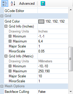
The appearance of the grid, including color, major and minor units, size and position, can be changed in the grid system configuration settings..
There are two sets of grid settings: One for inch drawing units and the other for metric.
Display Setup
The following options enable or disable the display of graphical aids.
-
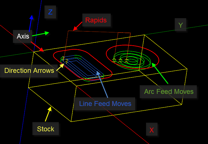
Show toolpaths - Enable / disable the display of lines representing the toolpaths.
-
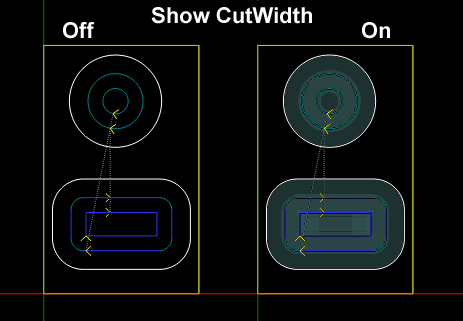
Show cut widths - Enable / disable the display of a shaded area depicting the width of cuts along the toolpaths based on the specified tool diameters.
-
Show stock - Enables / disables the display of the 3D representation of the block of material to be machined.
-
Show nests - Enables / disables the display of arrays of machining operations, defined in the Part
Nest properties. -
Show rapids - Enable / disable the display of dotted lines representing rapid moves (G0).
-
Show direction arrows - Enable / disable the display of arrows indicating the direction of travel of the tool.
-
Show grid - Enable / disable the display of the grid.
-
Show axis - Enable / disable the display of XYZ axis lines of the 3D view.
-
Anti-alias - Enable / disable anti-aliasing.
-
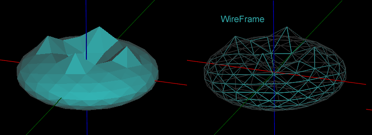
Wireframe - Toggle the display of 3D objects between shaded surfaces or wireframe mode.
-
Snap to grid - Enable / disable snap to grid.
-
Snap to object - Enable / disable snapping to other drawing objects.
-
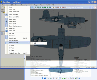
Windows opacity - A value between 0 and 100% (opaque) which allows tracing over reference drawings in windows behind the CamBam drawing.
-
XY / XZ / YZ Plane - Switches the view seen from above (XY - default), Front (XZ) or side (YZ). For now only the XY plane can be used to draw with the mouse.
-
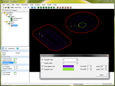
Toolpath view filter - Used to view step by step the tool path according to their order of execution or level in Z.
Toolpath index: if checked, you can view the tool path in order of their execution by changing the numerical value on the right.
In this example, the 7th toolpath is highlighted in yellow, previously cut toolpaths are shown in purple and uncut toolpaths are not visible.
Z depth index: if checked, you can view the tool path in order of Z level by changing the numerical value on the right. All tool paths on the same Z level will be displayed simultaneously.
If both Toolpath index and Z depth index are ticked, the toolpath will be filtered by index down to the maximum Z depth specified.
Cut toolpath color display or hide toolpaths cut previous to the current toolpath.
Toolpath color when checked, the current toolpath will be highlighted in the selected color on the right; If unchecked, the current toolpath will be displayed using the standard arc and line move colors.
Click on the colored rectangles to change the display color of the toolpaths.
You can also choose the line width by changing the width of
The Toolpath View Filter window can be kept open while manipulating the drawing, such zooming and panning the display.
Depending on the drawing’s
Display settings are available in the property grid by selecting the top level (Drawing) object of the drawing tree.
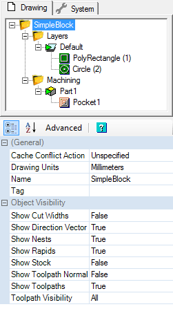
The display colors can be changed in the system configuration Colors group.

