Tutorial: Timing Pulley Profile
This tutorial demonstrates using Profile machining operations to generate an HTD5 timing pulley.
This tutorial uses the Plus Toolkit plugin to generate the timing pulley profile.
Download the files used in this tutorial
Step 1 - Insert an HTD timing pulley outline.
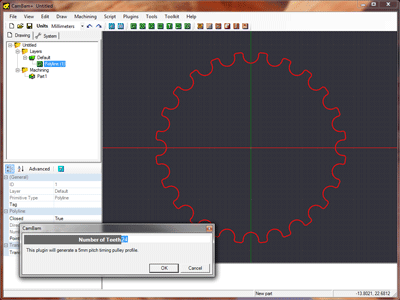
Use the new Plus Toolkit to generate a timing pulley by selecting the Toolkit - Timing Pulley menu item.
The plugin will prompt for the number of teeth for a 5mm pitch pulley, then insert a new curve with the center of the pulley about the origin.
ALT + double click will zoom the drawing to fit the view window.
Step 2 - Insert a Profile machine operation
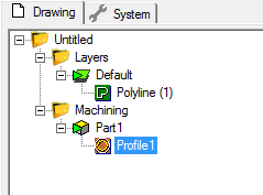
Select the pulley outline then click the Profile machining operation button  from the toolbar.
A new profile object will be created and displayed under the Machining folder in the drawing tree.
The object property window will display the profile’s properties ready for editing.
Change the Profile machine operation’s properties to the following:
| 2 | |
| 0.5 | |
| -5 | |
| 200 | |
| 100 | |
| 1.5 |
Note: Some properties such as
Clearance Plane may not be shown in the property grid.
Clicking the Advanced button at the top of the property grid will display all available properties.

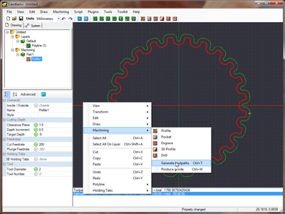
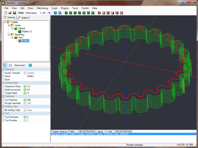
Generate the resulting toolpath for the profile; right click the drawing to bring up the drawing context menu, then select Machine - Generate Toolpaths.
To rotate the 3D drawing view, hold the ALT key then click and drag on the drawing.
To reset the view, hold the ALT key then double click the drawing.
Another rotation mode (
Step 3 - Creating the inner hole
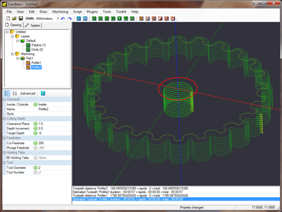
First draw a circle using the circle drawing tool  with the center on the origin with
Select the circle and insert another profile machining operation  .
.
Set the target depth and other properties to match the first profile operation.
Hint: A quick way to do this is to select Profile1 and copy it to the clipboard (using the context menu or CTRL+C). Then select Profile2 and use the Paste Format command from the context menu shown when right clicking Profile2, or use SHIFT+CTRL+V.
Change the
Again, right click the machine operation in the file tree and Generate Toolpaths.
Step 4 - Creating GCode
Before producing the gcode output, now would be a good time to save your drawing.
Visually inspect the toolpaths and double check the parameters of each machining operations.
To create a gcode file (post), right click to get the drawing menu then select Machine - Produce GCode.
CamBam will then prompt for the location of the gcode file to produce. If the drawing file has been saved, the default gcode file will be in the same folder as the drawing file, with a .nc extension.
If the destination file already exists you will be asked to confirm whether to overwrite it.
To control how the gcode file is produced, select the Machining folder from the drawing tree. The machining properties for this drawing will then be displayed in the object properties window.
