File Menu
File Open 
CamBam can read the following drawing file types:
- CamBam native file format (*.cb)
- Autodesk DXF files - up to AutoCAD 2000 format (*.dxf)
- 3DStudio files (*.3ds)
- Stereo Lithographic 3D meshes (*.stl)
- STEP files (*.stp, *.step)

- GCode files (.tap,.nc, etc)
- Gerber file (*.gbr)
Unrecognised file extensions are presumed to be GCode files.
Use the File - Open menu option to open the required file or drag and drop files from Windows Explorer onto the CamBam window.
When CamBam is installed, it will be associated with (*.cb) files, so these can be opened by double clicking them from Windows Explorer.
CamBam will also attempt to open any files passed to the application via the command line.
File New 
Creates a new blank file.
The interface will be reset, the default settings stored in the general configuration will be used.
Hint: If a Drawing Template is defined in the system configuration settings, this file will be used as template for the new drawing. The drawing template can contain useful default settings such as
Post Processor ,Fast Plunge Height andStock , as well as drawing objects and machining operations.
New from template
This will create a new drawing, based on an existing CamBam (.cb) file.
Template drawings are typically saved into the templates sub folder of the CamBam system folder. Use the Tools - Browse system folder menu to help find the templates location.
An example template drawing: nameplate.cb, is provided. This template allows the creation of a nameplate with raised lettering, commonly used for locomotive name plates. This template contains all the drawing objects and machining operations required. The default text can be quickly changed by double clicking the text object in the drawing view.
Changes made to a drawing based on a template will not affect the template file. To modify the template file, it will need to be opened from the template folder using File - Open.
Save, Save As 
Save your work using the menu File / Save or Save As.
Depending on the value of the File Backups configuration setting, a number of backup files may be generated for each file. These backups are located in the same folder as the saved drawing and will have extensions such as .b1, .b2 etc. with .b1 being the most recent backup.
Print 
Use this menu to print the drawing area.
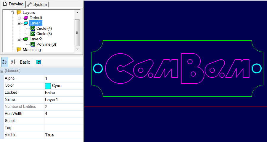
The colors and widths of the lines used for printing will be those defined in the
Be careful, with some printers, if the

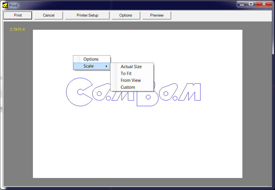
The print dialog window allows you to position the drawing on the sheet, change its zoom factor with the mouse or with a pop-up menu, and access printer settings and other options.

Pan and zoom: The zoom and pan functions by mouse work in the preview window in the same way as in the drawing area (see here) so that the area of interest can be positioned in the page; Alt + double-click in this preview window centers the drawing on the sheet.
At the top left, the zoom factor is displayed in yellow.
The zoom can be changed by turning the mouse wheel or using the Scale popup menu. You can use the Custom option to precisely set the desired zoom factor.
Printer setup button: Provides access to the selection panel and printer settings.
Print button: Provides access to the selection panel and printer settings, then starts printing via the OK button.
Preview button: Displays an exact preview of the print.
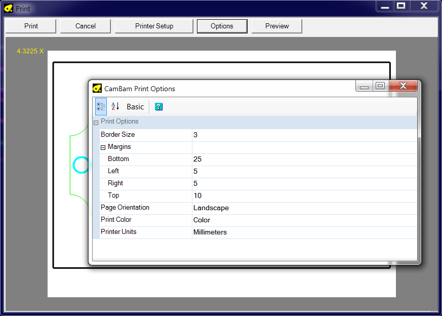
Options button: The context menu or the options button allows you to view the print options; these same options are also available in the general options of the program via the Tools / Options menu or via the Configuration folder of the system tab.

: Color, Monochrome (gray scale), or Black & White.
: If 0, the border display is disabled ; the values given in
: portrait (vertical) or landscape (horizontal)
Export
To DXF: Exports the current file to DXF format (AC1009 = AutoCAD R11 / R12)
To STL: All surface objects on visible layers will be merged into one file and exported to STL format (mesh) 